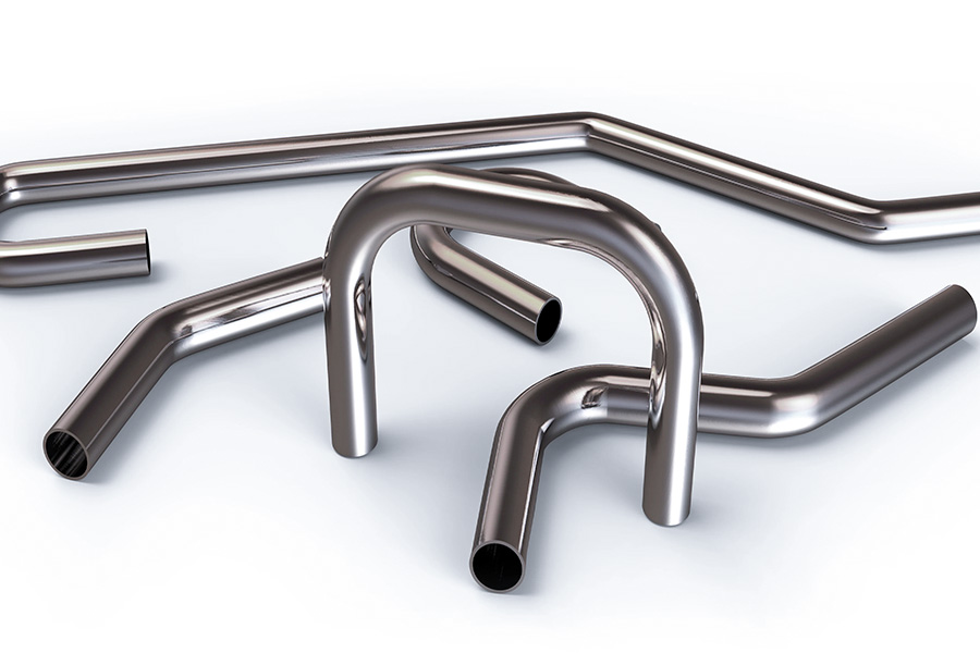
Tube bending design is a central technology in most of the industries such as mechanical manufacturing, automobile engineering, aerospace, and architectural ornamentation. It is not just about how the product looks outside, but it also has direct influences on the product’s performance, reliability and manufacturing cost. A well-designed tube bending can skillfully find space in complex spatial structures and meet various functional requirements. Meanwhile, it is also able to lower scrap rates and enhance production efficiency in the course of the production process. Below will discuss the main techniques of tube bending design.
What are the design techniques for Top tube bending?
The design of the bending of the top tube is a complex process with mechanics, material science and engineering practice, and its designing ability has to take into account many things. The following are the key skills and accurate analysis in the bending design of the top tube:
1. Reasonable choice of bending radius
- Minimum bending radius limitation: Select an appropriate minimum bending radius depending on the pipe material (e.g., stainless steel, carbon steel, copper, etc.) and thickness. The minimum bending radius is preferably not less than 2-3 times the pipe outer diameter to avoid excessive deformation or cracking.
- Standardized bending radius: Whenever feasible, adopt a standardized bending radius in order to keep mold cost low and process complexity low.
2. Accurate bending angle control
- Measurement and adjustment of the angle: Use highly accurate measuring equipment (angle gauges, laser rangefinders, etc.) to ensure the accuracy of the bending angle. Segmented measurement and correction are required for complex bends.
- Rebound compensation: Pipe will rebound during bending, and some amount of compensation angle must be reserved during designing stage. Compensation amount must be determined through experiments or empirical values based on the pipe material, wall thickness and bending radius.
3. Optimization of bending direction
- Radial and axial bending: Select the appropriate direction of bending (radial or axial) according to the intention and installation space of the pipe. Radial bending is mostly used in the section with confined space, whereas axial bending can more suitably be used to connect straight pipe sections.
- Multi-directional bending design: For multi-directional bent pipes, bending direction and sequence should reasonably be designed to avoid interference or pipe deformation beyond reasonable limits while bending.
4. Pipe wall thickness consideration
- Relationship between wall thickness and bending radius: Thinner wall pipes are more susceptible to deforming or cracking when bent, and a greater bending radius or supplementary processes (e.g., fillers, mandrels, etc.) must be selected.
- Wall thickness irregularity: Inspection of wall thickness is required for pipes with wall thickness irregularity before bending, and the impact of variations in wall thickness on bending quality must be considered in the design.
5. Application of auxiliary processes
- Fillers and mandrels: Sand, resin or other material is filled into the pipe’s interior, or a mandrel is applied to support the inner tube of the pipe to avoid deformation and crack under bending.
- Heating bending: For difficult-to-machine pipes (e.g., high-strength steel, titanium alloy, etc.), heating bending can be applied to reduce the yield strength of the pipe and improve the bending quality.
6. Choice of molds and equipment
- Special bending molds: According to the technical requirements and bending specifications of the pipe, select or design a special bending mold to ensure the accuracy of bending and surface quality.
- Bending equipment calibration: Calibrate the bending equipment periodically to ensure its accuracy and stability. For CNC bending equipment, it is necessary to compose a rational processing program to make the bending parameters optimal.
7. Inspection of bending quality
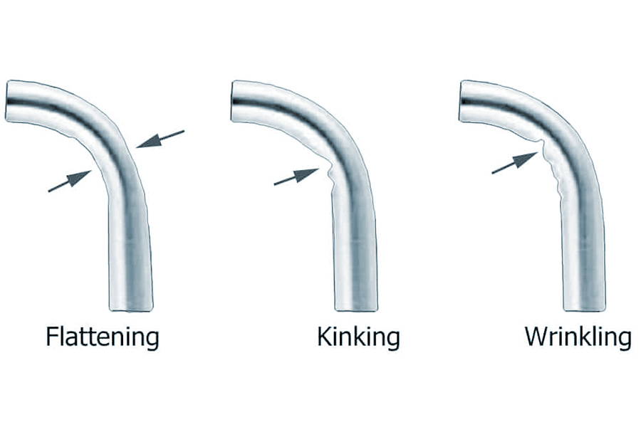
- Appearance inspection: Check whether there are wrinkles, indentations, other surface imperfections or cracks on the surface of the bent pipe.
- Dimension inspection: Check with measuring tools to determine whether there is dimensional precision in the bent pipe, e.g., bending radius, angle, length of straight section, etc.
- Non-destructive testing: In the case of large components, non-destructive tests such as ultrasonic and X-ray can be carried out to check whether there are internal faults inside the pipe.
8. Design optimization and simulation
- Finite element analysis (FEA): Model the pipe bending process, forecast the stress distribution, deformation and springback after bending, and improve the design parameters through the utilization of finite element software.
- Experimental validation: Test the operability of the design scheme through trial production in small quantities, and modify the design parameters according to the experimental result.
9. Material selection and pre-treatment
- Material characteristics: Choose pipes with good bending characteristics, e.g., material with low yield point and high ductility.
- Pre-treatment process: To bend pipes, pre-treatment processes like annealing and normalizing can be done to enhance their processing quality.
10. Bending process planning and sequence
- Segmented complex bending: In multi-directional complex bending, a reasonable plan should be made for the bending sequence so that no interference or over-bending of the pipe occurs while bending.
- Process parameter optimization for process quality improvement: From experimental or empirical data, optimize process parameters such as bending speed, pressure, temperature, etc. to enhance the bending quality.
Optimization of the scientific bending design instinct and computer assistance, and process optimization can significantly improve the product yield of the upper tube structure. Production efficiency will go on being improved further with regular process audits and machine maintenance.
How to Select the Optimum Die Radius for Different Materials?
1. Die radius formula calculation (golden rule)
The radius of the die (R) significantly affects the quality of bent pipe and level of material damage, and needs to be fully solved based on material properties + application conditions:
| Material type | Basic formula | Industry standard | Applicable scenarios |
|---|---|---|---|
| Carbon steel pipe | R=3×D (D is the pipe diameter) | ASME B16.49 | Petroleum/chemical pipelines |
| Aluminum alloy pipe | R≥4×D | AMS 2772G (aviation standard) | Aircraft fuel pipelines |
| Titanium alloy pipe | R=5~6×D (high temperature bending) | MIL-DTL-32567 (military industry) | Aerospace engine pipelines |
Formula optimization:
R=K×D+C
K: Material ductility coefficient (carbon steel 1.5~3, aluminum alloy 2~4, titanium alloy 3~6)
C: Compensation amount (when wall thickness>10mm, C=0.2×wall thickness)
2. Actual process points and parameters of 3 materials
(1) Carbon steel pipe mold radius selection
Primary parameters:
- Common temperature bending: R=3×D (such as DN50 pipe, R=150mm)
- Thick wall pipe (t/D≥0.1): R=4×D
- High temperature steam pipe: R=5×D+expansion joint
Process note:
- Annealing treatment must be carried out (600-650℃ insulation and slow cooling)
- UT detection crack depth after bending ≤10% of wall thickness
(2) Aluminum alloy pipe crack avoidance capacities
Optimization of mold radius:
- Thin wall (t≤3mm): R=4×D
- Thick wall (t>3mm): R=5×D
Anti-oxidation processes:
- Nitrogen shielding bending (oxygen content <50ppm)
- Hard chrome plating of mold surface (roughness Ra≤0.4μm)
(3) Titanium alloy tube high temperature bending standard
Military standard level (MIL-DTL-32567):
- Heating temperature: 600-800℃ (transformation zone of β phase)
- Insulation time: 1.5 minutes per millimeter of wall thickness
- Mold radius: R=6×D (preventing rebound deformation)
Items of required inspection:
- Grain size after bending ≤ Grade 5 (metallographic examination)
- Surface oxide layer thickness <0.02mm
3. Radius compensation scheme in different working conditions
Case 1: Small batch production with multi-specification
- Adaptive mold:
Use adjustable radius module (e.g., fan-shaped block combination mold)
Adjustment accuracy ±0.5mm (D=10-200mm pipe)
Case 2: High-precision aerospace pipe fitting
- Compensation design:
Actual radius = theoretical value × 1.03 (for titanium alloy rebound compensation)
Laser real-time calibration (accuracy ±0.1mm)
Case 3: Ultra-thin wall tube (t/D<0.05)
- Anti-collapse solution:
Fill low melting point alloy (such as Wood alloy, 70℃ melting point)
Add supporting rollers to the outer mold (pressure 0.5-1.2MPa)
What are the tube bending design process flows?
The tube bending design process flow includes mainly the following steps:
1.Requirement analysis
- Clarify the application situation, stress situation, medium (such as liquid, gas) and working condition (temperature, pressure, corrosiveness, etc.) of the pipe fittings.
- Determine fundamental parameters such as bending angle, radius, diameter of the pipe, wall thickness, etc.
2.Material selection
- Select proper materials (e.g., carbon steel, stainless steel, aluminum alloy, etc.) depending on requirements, considering mechanical characteristics (strength, ductility) and processability (easy to bend or not) of the material.
3.Process method determination
Select bending process:
- Cold bending: suited for small diameter and thin-walled tubes, inexpensive but there is rebound which must be compensated.
- Hot bending: in thick-walled or large-diameter tubes, the resistance to deformation is lowered through heating.
- Mechanical bending: (e.g., rolling bending, push bending, bending): select equipment (e.g., CNC tube bending machine) according to accuracy requirement and efficiency demand.
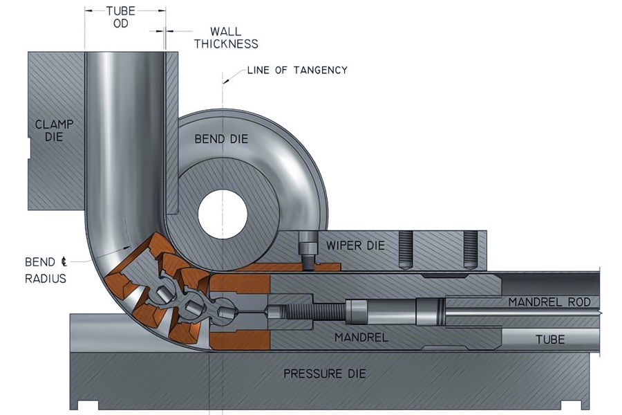
4.Mold and equipment design
- Design bending molds (e.g., clamps, bending mold, anti-wrinkle plate) to match the tube.
- Select or design the tube bending machine and input parameters (e.g., clamping force, bending speed).
5.Process parameter calculation
- Calculate bending radius (usually ≥1.5 times tube diameter to prevent wrinkling or bursting).
- Estimate rebound distance and calculate compensation angle through experimentation or simulation.
- Solve mandrel application (to prevent inner wall buckling) and lubrication plans.
6.Simulation and Verification
- Use finite element analysis (e.g. ANSYS) to simulate the bending process and study stress, wall thickness variation, etc.
- Design prototypes for bench-scale bending tests and examine for defects (ovality, cracks).
7.Process Documentation
- Develop working instructions, procedures, parameters, quality control criteria (e.g. tolerances, surface finish).
8.Production and Quality Test
- Check batch production uniformity and dimensionally inspect with CMM or optical inspection.
- Perform pressure testing and defect detection (e.g. X-ray) to qualify performance.
Where are the applications for tube bending design?
As it is the hub interconnect of pipeline systems, tube bending design has widespread uses in numerous primary industries. Its versatility and efficiency cannot be replaced in any project. The main application fields and significant technical parameters of pipe bending design are as follows:
1. Automobile industry
Exhaust system
- Typical components: manifold elbow, muffler connecting pipe
Technical specifications:
- High temperature resistant stainless steel (409/436L)
- Bending radius ≥ 2.5D (SAE J301 standard)
- Weld air tightness test (helium mass spectrometer ≤ 1×10⁻⁶ Pa·m³/s)
Fuel pipeline
Innovative design: multi-layer composite pipe bending (nylon outer layer + aluminum foil barrier layer)
Technical points:
- Cold bending to avoid delamination
- Shrinkage of inner diameter after bending < 3%
2. Aerospace field
Hydraulic pipeline
- Material selection: titanium alloy Ti-3Al-2.5V (AMS 4943 standard)
Military grade standard:
- Bending angle tolerance ±0.25° (MIL-DTL-83797)
- Surface roughness Ra≤0.8μm
Engine fuel pipe
Special process:
- Induction heating bending (350-400℃ temperature control)
- Inner wall electrolytic polishing (roughness reduction 40%)
3. Chemical and Energy Industry
Oil Pipeline
- Application scenario: S-type laying and bending of submarine pipeline
Key technologies:
- X65/X70 grade steel material
- Dynamic calculation of bending radius (DNV-OS-F101 standard specification)
- Nuclear power cooling system
Safety requirements:
- 316LN stainless steel (corrosion resistance in intergranular direction)
- Full coverage of non-destructive inspection (X-ray + ultrasonic)
4. Medical equipment industry
Minimally invasive surgery catheters
Precision molding:
- Superelastic nickel-titanium alloy (strain recovery over 95%)
- Inner diameter of cavity 0.5-3mm bending precision ±0.1mm
Imaging equipment pipeline
Special requirements:
- Non-magnetic materials (titanium/cobalt-chromium alloy)
- MRI compatibility test (magnetic field interference < 5 Gauss)
5. Architecture and decoration
Steel structure corridor
Large pipe bends application:
- Q345B steel pipe ≥500mm diameter
- Three-dimensional CNC bending (±2mm/10m error)
Decorative art modeling
Design trend:
- Hyperbolic stainless steel pipe bend (mirror polishing #8 level)
- Parametric design + robot bending
6. Emerging Technology Field
Hydrogen Energy Vehicle Hydrogen Storage Tank
Safety Specifications:
- Carbon Fiber Wrapped Aluminum Alloy Liner
- 70MPa High-Pressure Pipeline Bending (ISO 15869 Test)
- 3D Printed Conformal Cooling Pipe
Innovative Process:
- Topology Optimized Flow Channel Design
- Internal Bend Curvature ≥1.5D (to Prevent Powder Residue)
What Are the Hidden Costs in Multi-Plane Bending?
Hidden costs of multi-plane bending basically include the following factors, which are readily low-balled during initial planning but play an important role in production efficiency and total cost:
1. Cumulative error amplification (geometric accuracy loss)
Angular tolerance accumulation: With increasing number of bending surfaces, the angle tolerance is increasingly boosted (e.g., per the ISO 2768-m standard, ±0.25° of discrepancy on every surface and 5 bending surfaces adding up to ±1.25°), resulting in assembly or rework issues.
Tube length dimension deviation: The total deviation of the arc length of multi-plane bending may exceed the linear tolerance range, and additional compensation design or correction at a subsequent stage are required.
2. Tooling and fixture cost has increased significantly
Complex fixture development: Multi-plane bending requires a five-axis linkage fixture, and the development cost can be 3.8 times the single-plane fixture (e.g., from 20,000 yuan to 76,000 yuan).
Mold adjustment and debugging time: The tooling fixture changes are often required for different bending angles, and the debugging time is 30%~50% longer, affecting production capacity.
3. Detection complexity and cost have increased
Long-time 3D scanning: The calipers in the conventional manner cannot meet multi-plane detection, and 3D scanning (e.g., blue light scanners) is required. Inspection time of a single piece from 5 minutes to 25 minutes (full-size report required under GD&T requirements).
Special inspection tool investment: The complex bending pieces would entail special-inspection tools (e.g., contour templates) to be specially designed, and the investment is 2~3 times more.
4. Material and process loss
Increased scrap rate: Scrap rate of multi-plane bending in the debugging phase can reach up to 15%~20% (single plane is normally <5%), and thin-walled tube tend to wrinkle or crack.
Material pre-processing expense: in order to compensate for springback, additional tube blanks have to be sacrificed, and material utilization ratio will decrease by 10%~15%.
5. Concealed administrative expense
Process verification cycle is extended: there are a number of trial bends and simulation cycles, and R&D cycle is extended by 40%~60%.
Skill dependence: operators require greater training expense (five-axis equipment operation salary premium of 20%~30%).
Countermeasures
- DFM (Design for Manufacturing) optimization: reduce unnecessary bending surfaces and segmented welding in place of complex bending.
- Pre-compensation algorithm: predict springback through CAE simulation to reduce the cost of trial and error.
- Modular fixture: some general-purpose designs pay off in terms of tooling investment.
These invisible costs need to be anticipated ahead of time in project analysis, or the profit margin can be drastically reduced.
How to prevent thin-walled tubes (wall thickness <2mm) buckling during bending?
In the bending of thin-walled tubes (wall thickness <2mm), the most significant aspect is not to collapse or deform. Following are the customary procedures and precautions:
1. Support fill material
Solid fillers: Fill loose matter (e.g., sand, salt) or low-melting-point metals and drain them by heating or dissolving after bending.
Solid material: Pre-load with specialty bending glue (e.g., polyurethane), provide internal support when curing, and can be broken or dissolved at the end.
Mandrel/spring support: Position a soft spring or silicone mandrel to provide inner wall support, especially small radius bending.
2. Use special bending tools
Mandrel pipe bender: Use a pipe bender machine with a mandrel (e.g., ball-end mandrel) that gives support to the pipe wall in real-time during bending.
Rolling forming: Progressive bending by means of multiple sets of rolls to reduce local concentration of stress.
Hydraulic bulging: Press high-pressure liquid into pipe to resist compression force when bending.
3. Optimization of process
Heating aid: Local (200-300℃) heating of certain materials (e.g., aluminum and stainless steel) reduces yield strength and prevents rebound and cracking danger.
Slow bending: Reduce bending rate to prevent excessive temporary stress.
Segmented bending: Bend step by step in small angles a number of times to reduce the deformation in one time.
4. Tube pretreatment
Annealing: Pre-annealing to eliminate residual stress and increase ductility (especially for stainless steel and copper tubes).
Choose proper materials: use materials of good ductility preferentially (e.g., annealed copper tubes and soft aluminum tubes).
5. Other methods
External mold support: Use grooved molds or clamping blocks to limit tensile deformation of the outer side of the tube.
Lubrication and friction reduction: Apply lubricant between the mold and the tube to reduce uneven wall thickness caused by friction.
Shaping later: Collapse that is not too severe may be remedied with internal expansion pliers or pneumatic shaping.
Notes
- Filling compaction: In case of using sand, fill it tightly and shut the port to avoid looseness.
- Bending radius: Try to choose a radius ≥2 times the pipe diameter. Too small radius can easily lead to collapse.
- Material thickness uniformity: Eliminate the local weak points of the pipe.
Risk of collapse when bending thin-walled pipes can be basically avoided by taking the above measures in combination. The specific program should be selected according to the material type, bending radius and production conditions.
How to deal with scratches on the surface of the pipe when bending?
During thin-walled tube bending, surface scratches will affect the appearance quality and corrosion resistance and need to be addressed from the aspects of prevention and repair. The following are the specific solutions:
1. Prevention measures for scratches
(1) Optimization of molds and tools
Polishing molds: The surface roughness of the contact surfaces of bending molds, rollers, mandrels, etc. should be ≤Ra0.4μm (mirror-grade polishing).
Material selection: Molds with a lower hardness than the pipe (e.g., copper alloys, polyurethane coating molds) are employed to reduce hard friction.
Structural design: The mold contact parts have rounded transitions for avoiding scratches on sharp edges.
(2) Lubrication treatment
Apply lubricant: High-viscosity lubricating paste (e.g., bending oil containing molybdenum disulfide and graphite content) or PTFE (Teflon) spray is applied.
Film protection: Paste a temporary PE protective film before bending, or paste a peelable protective coating (tear off after bending).
(3) Process control
Reduce the bending speed: reduce the sliding friction between the pipe and the mold.
Adjust the clamping force: avoid excessive clamping force to damage the pipe wall.
Clean the environment: prevent metal chips, sand and other hard objects from adhering to the surface of the mold or pipe.
2. Scratch repair method
(1)Minor scratches (no exposed substrate)
Polishing:
Mechanical polishing: polish with fine sandpaper (≥800#) or wool wheel + polishing paste.
Electrolytic polishing: Can be used for stainless steel pipes to restore the surface finish.
Passivation treatment: Wipe the stainless steel pipe with nitric acid passivation solution to restore the oxide film.
(2)Deep scratches (exposed substrate)
Welding repair:
TIG repair welding: For copper, stainless steel and other materials, local repair welding and then grinding.
Cold welding method: For tubes of aluminum in order to avoid heat deformation.
Filling repair:
Metal epoxy resin: Fill the scratches and polish later (for non-pressure tubes).
Electroplating/spraying: Partial electroplating using nickel or spray painting (the surface should be pretreated).
(3)Functional damage (e.g., scratches on sealing surfaces)
Reprocessing: Remove the damaged layer by turning or honing (only if the wall thickness allows).
Replace the pipe section: If the key sections are severely scratched, cut off and replace directly.
3. Key points
- Material matching: The repair method must match the pipe material (e.g., do not apply copper-containing repair material to aluminum pipes).
- Anti-corrosion treatment: Reapply anodizing (aluminum pipes), passivation (stainless steel) or anti-rust paint after repair.
- Prevent secondary damage: Avoid scraping directly with hard tools during the repair.
4. Standard material response plan
| Pipe type | Prevention focus | Repair recommendation |
|---|---|---|
| Stainless steel pipe | Polishing mold + lubricant | Electrolytic polishing / TIG repair welding |
| Aluminum pipe | Polyurethane mold + low-speed bending | Cold welding / anodizing |
| Copper pipe | Low-friction coating mold | Soft cloth wheel polishing / silver brazing repair |
| Titanium pipe | Argon protection bending (anti-oxidation) | Laser cladding repair |
The impact of scratches on pipe performance may be minimized by: policy of prevention rather than repair. In the case of high-demand applications (aviation and medical, for instance), one should incorporate non-destructive testing (e.g., penetrant testing) following bending.
What to do when ovality is larger than is standard after bending?
Ovality (out-of-round) is a common defect after thin-walled tube bending, often due to asymmetric radial force. It can be corrected and prevented by the following:
1. Correct the elliptical deformation that has been caused
Mechanical shaping:
Subject a hydraulic bulger or inner mold support to force the deformed component back to circular cross-section (for local deformation).
For non-hardenable materials (aluminum, copper), a three-point rounding machine may be used for gradual correction.
Heat treatment shaping:
For stainless steel or titanium tubing, heat to recrystallization temperature (e.g., 800℃ for stainless steel) and then put in round mold to cool and form.
2. Preventive measures
Improve internal support:
Use hard mandrels (e.g., segmented ball head mandrels) or liquid filling (e.g., frozen water + dry ice) in the bending process.
Optimize process parameters:
Reduce the bending speed (e.g., ≤5°/s) to prevent non-uniform dynamic deformation.
Increase the thrust force (axial propulsion for material flow compensation).
Improve mold design:
Use multi-roller anti-flattening molds (e.g., 3-4 auxiliary rollers to enclose the outer wall of the pipe).
For precise pipe fittings, use CNC pipe bending machine + laser real-time correction system.
3. Permissible ovality standards
There are different specifications for different industries, for example:
Hydraulic pipelines: generally ≤5% (ovality = (Dmax-Dmin)/nominal diameter × 100%)
Aviation pipe fittings: ≤3%, should meet roundness test.
How to judge whether there are microcracks inside the tube?
Microcracks can be caused by material defects or excessive bending stress and need to be detected by the following methods:
1. Nondestructive testing (NDT) technology
| Method | Applicable scenarios | Detection accuracy | Cost |
|---|---|---|---|
| Penetrant testing | Surface open cracks (≤0.01mm) | High (surface only) | Low |
| Eddy current testing | Near-surface cracks of conductive materials | 0.1mm deep | Medium |
| Ultrasonic testing | Internal deep cracks (≥0.5mm deep) | 0.1mm level | High |
| X-ray imaging | Internal defects of complex structures | Micron level | Very high |
2. Simple detection method (applicable to small batches)
Dyeing method: Apply red penetrant, wipe and expose cracks with developer (suitable for cracks visible to the naked eye).
Air pressure test: Inflate the sealed pipe end to 1.5 times the working pressure, maintain the pressure for 5 minutes to observe whether the pressure drops.
Sampling after bending: Randomly cut the bending section for metallographic sectioning (destructive testing, but the most direct).
3. Measures to prevent microcracks
Material selection: Prefer annealed pipes with good ductility (such as 304 stainless steel in soft state).
Control the bending radius: Avoid sharp bends less than 2 times the pipe diameter (hard materials need ≥3 times).
Stress relief: Low temperature annealing after bending (such as stainless steel 300℃×1h).
How to reduce mold costs for small batch production?
For small batches (such as <100 pieces), mold investment can be reduced in the following ways:
1. Alternative mold solutions
General mold:
Use adjustable bending molds (such as modular roller sets, suitable for various pipe diameters).
3D print nylon or aluminum alloy molds (suitable for prototype verification, cost reduction of more than 60%).
Simple tooling:
Homemade wooden or epoxy resin molds (suitable for single tests, very low cost).
2. Process optimization and cost reduction
Mold-free technology:
Freeform Bending: guided by a multi-axis robot, no special bending mold is required (suitable for complex spatial curves).
Sandbag bending method: manual bending after filling with fine sand (suitable for large radius and low precision requirements).
Segment processing:
Complex bending pipes are disassembled into multiple standard elbows + straight pipe welding (reducing the need for special molds).
3. Collaboration and resource sharing
Outsourcing bending process: entrust professional bending factories to charge by piece (avoid purchasing molds by themselves).
Mold rental: share high-cost molds (such as aviation-grade mandrels) with peer companies.
4. Typical cost comparison
| Solution | Applicable batch | Mold cost | Precision |
|---|---|---|---|
| 3D printing aluminum mold | 1-50件 | ¥500-2000 | ±0.2mm |
| Universal adjustable mold | 50-200件 | ¥3000-8000 | ±0.1mm |
| Traditional steel mold | >500件 | ¥2万+ | ±0.05mm |
Conclusion
The tube bending design needs to comprehensively consider the material properties, process parameters and structural requirements. By rationally selecting the bending radius and angle, optimizing the bending direction and sequence, adopting auxiliary processes (such as filling or heating) and precisely controlling the amount of springback, defects such as cracking and wrinkling can be effectively avoided. At the same time, the design parameters should be optimized by combining simulation and experimental verification, and quality inspection and mold maintenance should be strengthened. Only in this way can the high-precision forming and stable performance of the tube in a complex spatial layout be achieved while ensuring the processing efficiency and yield rate, thus providing reliable support for industrial applications in multiple fields.
 📞 Phone: +86 185 6675 9667
📧 Email: info@longshengmfg.com
🌐 Website: https://www.longshengmfg.com/
Disclaimer
The content appearing on this webpage is for informational purposes only. LS makes no representation or warranty of any kind, be it expressed or implied, as to the accuracy, completeness, or validity of the information. Any performance parameters, geometric tolerances, specific design features, quality and types of materials, or processes should not be inferred to represent what will be delivered by third-party suppliers or manufacturers through LS’s network. Buyers seeking quotes for parts are responsible for defining the specific requirements for those parts. Please contact to our for more information.
Team LS
This article was written by various LS contributors. LS is a leading resource on manufacturing with CNC machining, sheet metal fabrication, 3D printing, injection molding,metal stamping and more. 
FAQs
What causes the springback of pipe bending?
The springback of pipe bending is the manifestation of the recovery of elastic deformation of the material. The fundamental reason is that the material still retains some elastic strain energy during the plastic deformation process. The specific influencing factors include: ① Material properties (the larger the elastic modulus E and the higher the yield strength σy, the more significant the springback of the material, such as titanium alloy has a 30-50% greater springback than low-carbon steel); ② Geometric parameters (the smaller the ratio of wall thickness t to pipe diameter D, the more obvious the springback); ③ Process conditions (too fast bending speed will reduce the plastic deformation time and increase the springback). In engineering, overbending (excessive bending 5-8°) or thermal correction is often used to compensate for springback.
2. What is the maximum bending angle of seamless pipes and welded pipes?
Due to the uniform structure of seamless pipes, extreme bending (such as cold bending 180°, hot bending 360°) can be achieved under reasonable processes, but R≥3D (D is the pipe diameter) must be met; welded pipes are affected by the weld, and their maximum safe bending angle is usually limited to: ① high-frequency welded pipes 90-120° (R≥5D); ② straight seam welded pipes 60-90° (R≥8D); ③ spiral welded pipes are only recommended for fine-tuning (≤30°). The key is to avoid the weld being in the maximum tensile zone, and post-weld heat treatment is required to improve plasticity.
3. Why does the mandrel design affect the surface finish?
As an internal support, the mandrel directly contacts the pipe wall. Its design factors include: ① material hardness (needs to be HRC10 higher than the pipe, usually carbide or chrome-plated steel); ② surface roughness (Ra≤0.4μm is recommended); ③ structural form (multi-ball joint mandrel reduces the contact area by 30% compared with the column type); ④ lubrication system (high-pressure oil film thickness ≥0.02mm). Poor design will lead to “fish scale pattern” (periodic scratches) or “orange peel effect” (local plastic deformation), which may cause sealing failure in precision systems such as hydraulic pipelines.
4. Which materials need to be hot-bent?
Materials that must be hot-bent can be divided into three categories: ① high-strength and difficult-to-deform materials (titanium alloy TC4 needs to be heated to 800-950℃ β phase region; tungsten-molybdenum alloy needs to be above 1200℃); ② thick-walled pipe fittings (carbon steel wall thickness > 50mm needs to be annealed and bent at 650-750℃); ③ special working conditions (Zircaloy cladding tubes for nuclear power need 400℃ argon protection to prevent oxidation). The hot bending temperature is usually controlled at 0.6-0.8Tm (melting point), and the risk of grain growth should be considered (for example, stainless steel needs to avoid the sensitization range of 500-800℃).


