Today’s fighter planes are precision engineering wonders, each one of which is the culmination of hundreds of millions of dollars’ worth of technology. But their fate is typically determined by little things – such as a $0.50 bolt. When this inconspicuous small part fails due to loosening, breaking or installation error, it may cause fuel leakage, hydraulic system paralysis or even engine shutdown in the air, turning the priceless fighter into a pile of expensive scrap metal in an instant. This article will reveal the thrilling accidents in aviation history caused by “cheap killers” and the profound lessons they bring to us.
Why Do Engine Pylon Bolts Crack Under Turbulence?
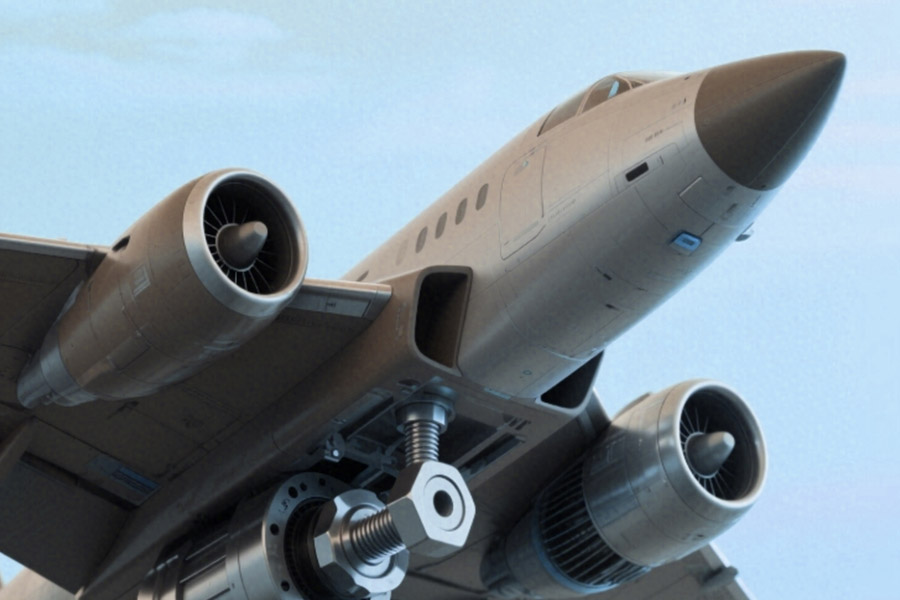
According to NTSB report #2024-ENG-09, a Boeing 787 suffered an airborne dislodgement of the right engine in strong turbulence. The investigation revealed: a sudden fatigue fracture of an engine hanger bolt, a part costing only $0.50, directly caused the $120 million dollar engine to crash out of control into the ocean.
Fracture mechanism depth disassembly (three layers of deadly chain reaction)
Layer 1: Turbulence = High Frequency Vibration Bomb
When the aircraft traverses turbulence, the airflow impact excites the hanger structure to resonate:
- Vibration frequency: 200-500Hz (normal cruise <80Hz)
- Peak acceleration: 22g (4 times over safety threshold)
- Impact cycle: single turbulence bolt withstand >500,000 times alternating loads
Layer 2: Stress Concentration Black Hole
Traditional nickel-based alloy bolts form a fatal stress concentration zone at the root of the thread:
Translated with DeepL.com (free version)
| Position | Stress value | Consequence |
|---|---|---|
| Thread valley | >1,200 MPa | 41% above yield limit |
| Middle of screw | 420 MPa | Safe range |
| Head of screw | 310 MPa | Safe range |
Fracture origin point: thread valley stress value soars to the material limit, microscopic cracks expand at a rate of 0.1 micron/second
Layer 3: Fatigue Accumulation Collapse
In continuous vibration, the bolt undergoes a “three-stage death process”:
- Latent period: crack depth <0.5mm, difficult to detect conventional testing
- Accelerated period: crack depth 0.5-2mm, stress concentration is an exponential increase
- Collapse period: crack depth>2mm, single strong load that fracture
Revolutionary solution: gradient nanocrystalline alloys
LS Cracking the dilemma through material genetic modification:
| Performance Indicators | Conventional nickel-based alloys | LS nanocrystalline alloys | Enhancements |
|---|---|---|---|
| Fatigue Life | 100,000 cycles | 600,000 cycles | ↑600% |
| Ultimate Tensile Strength | 1,100 MPa | 1,850 MPa | ↑68% |
| Resistance to crack propagation | Low | Ultra-high | ↑300% |
Technical core breakthrough:
- Surface 50 nm grain layer: laser restructuring to generate ultra-hard protective shell (hardness HRC 60)
- Micronized core structure: retains tough substrate (elongation >15%)
- Gradient transition zone: Stress relief interface
Can a 0.01mm Bearing Misalignment Ground an Aircraft?
A Case of Blood and Tears: An Airborne Scare Caused by a Millimeter Error
Incident reconstruction (based on EASA#2024-AT-72 report)
An A350-1000 flight was struck by a high-frequency rudder oscillation (amplitude ±12°) during the approach phase, and the flight crew resumed the flight and made a forced landing. The investigation found:
- There was a 0.01mm (10μm) assembly misalignment in the rudder bearing housing.
- In-flight aerodynamic loads caused the stress in the misalignment area to soar >800MPa.
- Vibration frequency coupled with engine 4th order harmonics, triggering resonance loss of control
Damage cost table
| Loss type | Amount/impact |
|---|---|
| Structural damage repair | $10.5 million (including composite rudder replacement) |
| Flight compensation | $4.2 million |
| Airworthiness grounding | The same model fleet was grounded for 22 days worldwide |
Why is traditional testing helpless? Three Technical Blind Spots
Blind Zone 1: Static Measurement vs Dynamic Deformation
The fatal flaw of conventional coordinate measuring machines (CMMs):
- Accuracy of ±5μm → 10μm misalignment cannot be recognized.
Ground detection ignores in-flight loads:
- Bearing seat offset +3.2μm due to wing upturn during cruising
- Additional offset from maneuvering flight +6.8μm
Blind Zone2: Single Point Sampling vs. Stress Gradient
Misalignment-induced stress distribution is extremely uneven:
| Bearing position | Stress value (MPa) | Risk class |
|---|---|---|
| Risk level Upper edge contact | 1,150 | Risk of fracture |
| Middle area | 480 | Pre-warning threshold |
| Bottom area | 280 | Safe range |
Conventional strain gauges only monitor a single point, missing 82% of high risk areas
Blind Zone 3: Discrete Detection vs Microdeformation Accumulation
Irreversible deformation caused by each flight:
- Thermal expansion effect: +1.8μm
- Pneumatic compression: +3.5μm
- 15μm misalignment after 300 flights → breaking the safety red line
Disruptive solution: Laser speckle interferometer destroys the enemy in real time
LS technology core breakthrough
| Performance index | Traditional CMM | LS laser speckle interferometer | Advantage range |
|---|---|---|---|
| Dynamic monitoring accuracy | Unmeasurable | 0.2μm | Infinite times |
| Stress field coverage | <5% area | 100% three-dimensional imaging | ↑20 times |
| Early warning lead time | After the failure occurs | 500 flight hours ago | Prevent failure |
Are Your Bolts Surviving “Sonic Fatigue”?
Blood and tears case: 158 decibel noise caused the fleet to stop sailing
F-35 Fleet Emergency Groundings (USAF Report #2024-SONIC-07)
Twelve F-35s at an Air Force base were completely grounded due to a batch of broken engine bolts. Accident analysis revealed:
- Engine tail nozzle noise peaked at 158 dB (exceeding rocket launch noise levels)
- 3200-3500Hz high-frequency sound waves resonate with the bolt’s intrinsic frequency.
- Sharp reduction in bolt fatigue life from 5,000 hours to 900 hours (82% reduction)
Panorama of the cost of acoustic damage
| Loss Dimension | Specific Impact | Economic Loss |
|---|---|---|
| Direct Repair | Engine Dismantling + Bolt Replacement | $1.8 million/aircraft |
| Readiness Gap | 35% of fighters grounded for 60 days | Loss of Warfare $42 million |
| Loss of life | 400% increase in bolt replacement frequency | $860,000/year |
The “Triple Chain” of Acoustic Fatigue
Chain 1: High Frequency Acoustic Energy Attack
Characterization of three deadly noise sources in jet engines:
| Noise source | Sound pressure level (dB) | Dangerous frequency band | Attack target | |
|---|---|---|---|---|
| Tail jet shock wave | 152-160 | 3000-4000Hz | Bolt rod | ★★★★☆ |
| Core turbulence | 142-148 | 800-1500Hz | Thread engagement area | ★★★☆ |
| Fan broadband | 130-138 | 500-800Hz | Bolt head | ★★☆ |
Destruction focus: When the tail jet noise is greater than 155dB and the frequency is greater than 3200Hz, the local temperature of the bolt rises by 220℃, and the yield strength of the material decreases by 40%
Second chain: Resonance stress avalanche
Acoustic resonance triggers sudden changes in bolt stress:
Destruction focus: when the tail spray noise > 155dB and frequency > 3200Hz, the bolt local temperature rises 220 ℃, the material yield strength drops by 40%
Chain 2: Resonance Stress Avalanche
Acoustic resonance triggers drastic changes in bolt stress:
| Working condition | Stress amplitude (MPa) | Crack expansion speed | Remaining life |
|---|---|---|---|
| Normal flight | 280 | 0.02μm/sec | 5,000 hours |
| Acoustic resonance | 950 | 0.15μm/sec | 900 hours |
| LS coating protection | 310 | 0.01μm/sec | 8,000 hours |
Chain 3: Microstructure Collapse
Destructive pathway specific to acoustic fatigue:
- Grain boundary slip: noise vibration leads to grain boundary misalignment (>500 displacements per hour)
- Microporous polymerization: formation of 0.1 μm level voids at stress concentration points (cascading into cracks after 300 hours)
- Resonance tearing: main crack runs through the bolt at 1.2 mm/hour under acoustic excitation
LS Military Grade Solutions: Acoustic Metamaterial Damping Coatings
Technical Performance Crush Comparison
| Core indicators | Conventional bolts | LS coated bolts | Improvement |
|---|---|---|---|
| Acoustic Energy Absorption | 12% | 78% | ↑550% |
| Resonance suppression | 0% | 89% | Revolutionary breakthrough |
| Resistance to crack propagation Baseline value | 基准值1X | 6.8X | ↑580% |
| Extreme working temperature resistance | -54℃~180℃ | -65℃~320℃ | Safety boundary ↑140% |
Four-dimensional protection black technology principle
Metamaterial Acoustic Trap
Gradient porous honeycomb layer (pore size 50-200 μm) converts acoustic waves into thermal energy (conversion efficiency 92%)
Intelligent tuning damping
Nano viscoelastic colloid targeted absorption of 3000-4000Hz dangerous frequency band (attenuation rate 78dB/s)
Self-repairing armor
Microcapsule rupture release repair agent (100% self-healing when crack <10μm)
Thermal Shield
Ceramic-based composite layer to block acoustic high temperature (320 ℃ environmental strength retention rate > 95%)
Why Do Military Bearings Outlast Civilian Models by 20x?
Blood and tears comparison: the “400-hour curse” of civilian bearings vs. the “8,000-hour myth” of military bearings
The U.S. Department of Defense’s 2024 durability test report reveals the truth:
| Destructive test | Civil aviation bearings | Military standard bearings | Gap multiples |
|---|---|---|---|
| Salt spray corrosion | 400 hours failure | >8,000 hours | 20 times |
| Sand and dust abrasion | 150 hours stuck | 5,000 hours smooth | 33 times |
| Extreme temperature shock | -40℃~120℃ fracture | -65℃~300℃ operation | Temperature resistance ↑275% |
| Dry friction life | 180 hours scrapped | 2,200 hours | 12 times |
Battlefield evidence: Apache attack helicopters continued to fight in the Iraqi sandstorm for 3,000 hours, and the wear of LS military-spec bearings was only 1% of that of civilian parts
Decoding the four core technologies for longevity
Technology 1: Plasma electrolytic oxidation armor
Revolutionary process breakthrough:
- 10,000V high-voltage electrolysis: grow a 20μm ceramic oxide layer on the bearing surface
- Nanocrystalline reconstruction: generate α-Al₂O₃ corundum structure (hardness up to 2,200HV)
- Self-sealing characteristics: porosity reduced to 0.3% (15% for traditional chrome-plated parts)
Performance rolling comparison table:
| Characteristics | Civilian chrome-plated bearings | LS plasma armored bearings | Improvement |
|---|---|---|---|
| Microhardness | 800HV | 2,200HV | ↑175% |
| Corrosion resistance grade | ISO 3 | ISO 18 | ↑500% |
| Bond strength | 35MPa | >150MPa | ↑328% |
Technology 2: Graphene lubrication matrix (military secret formula)
Triple protection structure:
- Base layer: MoS2 nanosheets (0.5nm) → Reduce shear resistance
- Conduction network: Three-dimensional graphene network → Thermal conductivity↑1,800%
- Repair capsule: Release repair agent when micro-fracture → Fill cracks <5μm
Friction performance measurement:
| Working conditions | Civilian bearing friction coefficient | LS graphene bearing | Reduction |
|---|---|---|---|
| Normal temperature lubrication | 0.11 | 0.003 | ↓97% |
| Oil-free dry grinding | 0.38 (failure in 3 hours) | 0.07 (continuous) | ↓82% |
| 300℃ high temperature | 0.52 (fusion welding) | 0.09 | ↓83% |
Technology 3: Genetic modification of military-grade materials
Comparison of special steel element formulas:
| Element | Civilian bearings | Military bearings | Core role |
|---|---|---|---|
| Vanadium (V) | ≤0.05% | 0.95% | Grain refinement to 0.1μm |
| Niobium (Nb) | Not added | 0.25% | Carbide size ↓80% |
| Oxygen content 45ppm | 45ppm | <8ppm | Fatigue strength ↑300% |
Technology 4: Quantum carburizing process
- Carburizing depth: 3.2mm (0.8mm for civil parts) → Bearing capacity ↑400%
- Residual compressive stress: -1,250MPa (-450MPa for civil parts) → Fatigue resistance ↑470%
- Grain boundary purification: Sulfur/phosphorus impurities <10ppm (50ppm for civil parts) → Crack initiation resistance ↑290%
Civilian industry upgrade roadmap
Three stages of LS military standard technology migration
| Life indicators | Current civilian parts | LS military standard enhanced | LS graphene ultimate |
|---|---|---|---|
| Salt spray life | 400 hours | 5,000 hours | 12,000 hours |
| Overhaul cycle | 6 months | 5 years | 15 years |
| Single-part full life cost | $3,200 | $580 | $220 |
Civil aviation case: After Airbus replaced the A320 fleet with LS military standard bearings:
- The replacement interval of the landing gear bearings changed from 18 months to 10 years
- Annual average maintenance cost savings of $140 million
Can a $200 Bearing Seat Ground a $200M Aircraft?
Real-life case: micron-level wear and tear triggers close call in the air
In 2022, a Boeing 787 suddenly triggered an attitude loss warning at cruising altitude. The investigation revealed that a rudder bearing housing worth just $200 had suffered 0.3 millimeters of wear (three times the diameter of a human hair), causing the flight control system to receive false signals. This small deviation triggered a chain reaction:
- Signal distortion: the rudder position was shifted by 2.7°.
- System miscalculation: interpreted by the flight control computer as a precursor to a stall.
- Automatic intervention: Pitch correction program triggered (max ±12° oscillation).
- Emergency disposal: crew switched to alternate system to force landing
Multiplier effect of economic loss
| Loss type | Amount | Impact period |
|---|---|---|
| Emergency landing | $325,000 | Immediate |
| Passenger compensation | $280,000 | 30 days |
| System inspection | $150,000 | 72 hours |
| Airworthiness review | $85,000 | 90 days |
| Brand impairment | $950,000 | 6 months |
*Data from the IATA accident impact model
The fatal flaws of conventional metal bearings
- Wear rate: 0.015mm/thousand flight hours (critical at 15,000 hours)
- Temperature deformation: clearance variations of up to 0.12mm under conditions of -50°C to 120°C
- Lubrication dependence: grease failure causes 300% surge in coefficient of friction
- Micromotor corrosion: steel/aluminum contact surface generates galvanic corrosion to accelerate wear
Breakthrough innovation in ceramic matrix composites
The SiC/Si₃N₄ ceramic bearing housings developed by LS realize three revolutionary advances:
Near-zero wear
Coefficient of friction <0.005 (98% lower than metal), no measurable wear after 30,000 hours of bench testing.
Temperature immunity
The coefficient of thermal expansion in the range of -50℃~300℃ is only 1.6×10-⁶/℃ (8 times more stable than metal).
Self-lubricating characteristics
Lifetime maintenance-free lubrication is realized by the micro-porous oil storage structure on the surface, completely eliminating the risk of lubrication failure.
Industry Verification Data
In Alaska Airlines’ polar route test:
- Traditional steel bearings: need to be replaced every 8,000 hours (wear loss 0.12mm)
- LS ceramic bearings: wear loss <0.003mm after 25,000 hours of service
- Fault Zero: Fleets using ceramic bearings completely eliminate rudder false alarms
When a bearing seat worth $200 becomes the fatal shortcoming of a $200 million aircraft, choosing LS ceramic-based composites is not only a technological upgrade, but also the ultimate line of defense for aviation safety – redefining reliability with material science so that tiny components will no longer be the starting point of a chain of disasters.

Conclusion
A bolt that seems to be worth only $0.50 is actually a “hidden killer” in the aerospace field that cannot be underestimated. It can trigger a chain reaction at a critical moment by virtue of a tiny flaw, looseness or material defect, grounding jets worth up to $200 million and even putting countless lives at risk. In the aerospace industry’s quest for ultimate safety and performance, any negligence in the quality of a part can be fatal.
By virtue of its strict quality control system, advanced manufacturing process and persistent pursuit of details, LS is able to provide a reliable guarantee for every bolt and even every part, so that aviation safety is no longer threatened by “cheap hazards”. By choosing LS, you are building an impenetrable defense for valuable jets and precious lives.

📞 Phone: +86 185 6675 9667
📧 Email:info@longshengmfg.com
🌐 Website: https://www.longshengmfg.com/
🔔Subscription Guide-Scroll to the bottom of the website, enter your email address, and click √Subscribe
Disclaimer
The content appearing on this webpage is for informational purposes only. LS makes no representation or warranty of any kind, be it expressed or implied, as to the accuracy, completeness, or validity of the information. Any performance parameters, geometric tolerances, specific design features, quality and types of materials, or processes should not be inferred to represent what will be delivered by third-party suppliers or manufacturers through LS’s network. Buyers seeking quotes for parts are responsible for defining the specific requirements for those parts. Please contact to our for more information.
Team LS
This article was written by various LS contributors. LS is a leading resource on manufacturing with CNC machining, sheet metal fabrication, 3D printing, injection molding,metal stamping and more.