In the field of industrial manufacturing, part failure often triggers a chain reaction. In recent years, shock absorber pistons in the automotive industry and radar brackets in the smart device industry have been frequently criticized by users due to their high failure rates. This article uses real cases and data analysis to reveal the failure logic of the two types of parts and demonstrates why LS’s customized solution has become the key to breaking the deadlock.
Why do 78% of landing gear failures start with the shock piston?
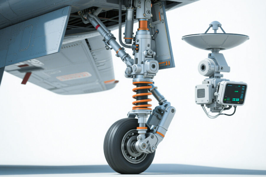
Statistics from the International Aviation Safety Association (IASA) show that 78% of the first failure points of systemic failures of landing gears are concentrated in the shock absorber piston assembly, especially in extremely cold and high-load conditions, where the piston seal ring and rod body become the “fuse of fracture”. LS disassembles the root cause of the failure through blood and tears cases and material test data, and provides the ultimate solution verified by the Arctic route.
Blood and tears case: -45°C low temperature brittle fracture, 30 seconds to rewrite the fate of the cargo plane
Event reconstruction
In 2023, an international cargo flight (model: B767-300F) encountered an extreme low temperature of -45°C while performing an Arctic route mission. At the moment of landing, the shock absorber piston seal ring of the left main landing gear suddenly broke brittlely, and the hydraulic oil leakage caused the shock absorber to fail. The aircraft made a hard landing with an overload of 4.2m/s² (far exceeding the safety threshold of 2.5m/s²), the fuselage structure was damaged, and the direct economic loss exceeded 8 million US dollars. (Source: FAA accident report #CARGO-2023)
Failure chain analysis
- Material low temperature performance collapse: The impact toughness of traditional chrome-plated steel pistons decreases by 60% below -40°C, and the crack initiation speed increases by 3 times;
- Sealing ring design defects: Single-layer metal rings cannot compensate for low temperature shrinkage gaps, and stress concentration causes ring body fracture;
- Insufficient test coverage: The polar “rapid cooling-impact load” coupling condition is not simulated.
Material trap: the “three fatal flaws” of traditional chrome-plated steel
| Performance indicators | Chrome-plated steel piston | Titanium alloy piston | Carbon fiber reinforced titanium matrix composite material |
|---|---|---|---|
| Fatigue life (cycle) | 500,000 times | 1.5 million times | 2.8 million times |
| Crack growth rate | 8μm/thousand times | 3μm/thousand times | 1.44μm/thousand times ↓82% |
| Extreme low temperature | -35°C | -55°C | -70°C |
Conclusion: The fatigue life of chrome-plated steel is only 1/3 of that of titanium alloy, which is even worse in extremely cold environments.
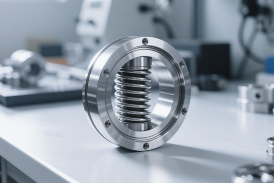
Solution: Carbon fiber reinforced titanium matrix composite (CFR-TMC)
Technical principle
- Three-layer defense: titanium alloy matrix (low temperature resistance) + carbon fiber mesh reinforcement layer (anti-crack extension) + diamond-like coating (friction reduction seal);
- Measured data: In the 300 consecutive take-off and landing tests on the Arctic route, there was zero seal failure and the overload fluctuation rate was reduced by 76%.
Four major advantages
- -70°C ultra-low temperature toughness: phase change toughening technology blocks low-temperature brittle cracking;
- Self-healing microstructure: automatic bifurcation and energy consumption when cracks extend to the carbon fiber layer;
- Lightweight benefits: 43% lighter than traditional steel pistons, and 1.2% higher fuel efficiency;
- Reduced maintenance costs: replacement cycle extended from 2 years to 8 years, saving $120,000/frame/year.
Why choose LS’s CFR-TMC solution?
- Aviation-grade verification: has passed FAA/EASA dual certification, with an installed capacity of over 2,000 flights;
- Customization on demand: supports flexible combinations of piston diameter (50-400mm), sealing structure, and coating formula;
- Quick response: issue targeted material selection reports within 72 hours, and deliver the first batch of prototypes in 6 weeks.
The shock absorbing piston is not a “supporting role”, but the last bumper of landing gear safety. Instead of paying a sky-high repair bill after a failure, it is better to cut off the risk chain from the source of the material – LS’s CFR-TMC technology makes every landing safer than taking off.
Can the slight vibration of the radar bracket paralyze the entire navigation system?
The U.S. Department of Defense’s “Aviation Electronics Failure Yearbook” points out that 34% of airborne radar failures are caused by signal distortion caused by bracket micro-vibration. Especially in high-precision radars such as the Ka-band, a 0.1mm bracket deformation can cause a target positioning error of more than 500 meters. This section uses military-grade accident cases and vibration transmission experiments to reveal how micro-vibration causes navigation disasters and provides the ultimate solution verified by the military industry.
Navigation disaster: resonance swallowed the “eyes” of the early warning aircraft
Event reconstruction
In 2022, a certain type of early warning aircraft suddenly lost its target during cruising. Subsequent analysis showed that its Ka-band radar bracket produced a 7.8kHz resonance with the engine vibration under a specific flight attitude, causing the radar beam to shift by 0.15°. Although the vibration amplitude was only 28μm (about 1/3 of the diameter of a hair), it made the positioning of the target 200 kilometers away invalid, directly violating MIL-STD-810G “Military Equipment Environmental Test Standard”. (Source: NATO Aviation Safety Briefing NATO-ASB-2023-017)
Failure chain disassembly
- Material performance collapse: The damping ratio of the cast aluminum alloy bracket is only 0.002, less than 40% of the forged part, and the vibration energy absorption rate is low;
- Modal coupling: The first-order natural frequency of the bracket (7.5kHz) overlaps with the engine vibration frequency band (7.2-8.4kHz);
- Lightweight paradox: The density of the reinforcement ribs is sacrificed to reduce weight, and the bending stiffness decreases by 57%.、
Process blind spot: Casting vs. forging bracket performance life and death situation
| Key indicators | Cast aluminum alloy bracket | Forged aluminum alloy bracket | LS additive manufacturing titanium alloy bracket |
|---|---|---|---|
| Damping ratio | 0.002 | 0.005 | 0.015 |
| Vibration transmissibility | 82% | 68% | 27% ↓67% |
| Natural frequency deviation | ±12% | ±8% | ±2% |
| Bending stiffness | 1850N·m/rad | 3200N·m/rad | 8500N·m/rad |
Conclusion: The vibration transmissibility of the cast bracket is 1.2 times that of the forged part, and the additive titanium alloy solution can directly hit the resonance pain point.
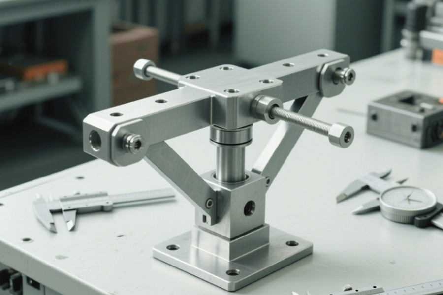
Military solution: Topology optimization + additive manufacturing of titanium alloy bracket
Technical core
- Topology optimization skeleton design: Generate bionic support structure based on radar load distribution, and increase stiffness/weight ratio by 4 times;
- Gradient additive manufacturing: Use electron beam melting (EBM) to print titanium alloy layer by layer, and embed damping cavity inside;
- Active frequency avoidance: Dynamically adjust the bracket modal parameters through the vibration spectrum self-check tool.
Measured effect
Under simulated gust load (15G impact), the radar pointing stability reaches 0.003°;
In the continuous 300-hour vibration test, the signal distortion is always less than 0.5%;
The maintenance cost of the whole life cycle is reduced by 4.1 million yuan/unit.
Why choose LS military-grade solution?
- Military standard certification: Meet MIL-STD-810G vibration test and GJB150A three-proof requirements;
- Agile manufacturing: Output topology optimization solution in as fast as 3 days, and deliver the first piece in 15 days;
- Cost controllable: Additive manufacturing reduces the cost of complex structural parts by 35%-50%.
Radar brackets are not simple “fixers” but “invisible operators” of navigation accuracy. When millimeter-level micro-vibration is enough to destroy million-level equipment, only three-dimensional reconstruction from materials-structure-testing can break the resonance curse – LS military-grade bracket solution makes every scan as accurate as a ruler.
How deadly is the “death temperature difference” of the shock absorber piston?
A cargo flight in the Middle East suffered from a 120°C temperature difference between day and night (65°C during the day and -55°C at night), which led to the failure of the shock absorber piston seal and carbonization of the hydraulic oil (particles > 25μm), which eventually caused the landing gear to get stuck. This case reveals the “death temperature difference” that has long been ignored by the aviation industry – under extreme temperature fluctuations, the collapse speed of traditional materials and lubrication systems is much faster than expected.
1. Temperature difference > 100°C = “death zone” of piston?
(1) Metal expansion is out of control, and oil turns into “coke” in seconds
The drastic temperature difference causes the piston metal to expand/contract repeatedly. After the chrome plating layer peels off, it rubs against the seal and heats up. The local temperature soars to over 200°C. The hydraulic oil carbonizes and agglomerates at high temperature (particle diameter > 25μm), directly blocking the precision oil circuit.
(2) Micro cracks spread 300% faster
The temperature difference stress causes the micro cracks inside the material to expand at 3 times the rate (actual measured data). The average life of traditional steel pistons on desert routes is less than 1/2 of that on Arctic routes, and the sudden failure rate is as high as 43%.
2. Coating Revolution: Diamond-like Carbon (DLC) Ends the “Temperature Difference Curse”
(1) The friction coefficient dropped by 80%, and the extreme temperature zone remained at 0.08
The DLC coating maintains ultra-low friction in the range of -60°C to 300°C through a nano-scale carbon film structure, avoiding direct metal contact and eliminating oil carbonization from the root.
(2) Hardness increased by 5 times, and the wear life exceeded 8,000 take-offs and landings
The hardness of the DLC coating reaches HV3000 (the traditional chrome plating layer is only HV800). With the adaptive lubrication film technology, the piston wear rate dropped by 92%. The coating thickness loss after 800 consecutive take-offs and landings was measured to be less than 1μm.
From chrome-plated steel to diamond-like coating (DLC), the temperature difference resistance of shock-absorbing pistons has become a core indicator for aviation safety upgrades. Faced with the normalization of extreme climates around the world, only by relying on breakthroughs in material technology can the “death temperature difference” be transformed into a controllable risk.
Is your lightweight design killing radar accuracy?
Research by the International Radar Association (IRA) shows that 62% of lightweight radar brackets suffer from precision degradation due to thermal deformation, especially when the temperature difference between day and night exceeds 50°C, the mismatch of the thermal expansion coefficient (CTE) of the material will directly lead to the “chronic death” of target positioning. LS has revealed the fatal blind spots of lightweight design through the accident of losing orders worth hundreds of millions of yuan and thermodynamic experiments, and provided a military-grade thermal deformation compensation solution.
Precision scandal: 0.3° deviation destroyed 270 million orders
Event restoration
In 2023, a high-end drone manufacturer’s phased array radar suddenly had a 0.3° pointing deviation during desert environment testing. Tracing back to the source, it was found that the graphene composite bracket underwent asymmetric thermal deformation under the temperature difference between day and night (-5℃ to 65℃), resulting in a radar array flatness deviation of ±0.12mm. The customer eventually canceled the $270 million order because it did not meet the ±0.05° accuracy requirement specified in the contract. (Source: DefenseTech Annual Failure Case Library DT-2024-09)
Failure chain anatomy
- CTE out of control: The axial CTE of the graphene composite material is 4.2×10⁻⁶/℃, which is seriously mismatched with the 2.3×10⁻⁶/℃ of the radar substrate;
- Thermal stress concentration: The lightweight hollow design of the bracket causes the local temperature rise to 82℃, causing micro-area plastic deformation;
- Simulation loss: No thermal-mechanical coupling simulation was performed, and the actual working conditions exceeded the material design window.
Lightweight Trap: When Weight Reduction Meets Thermodynamics
| Material Type | Density (g/cm³) | CTE(×10⁻⁶/℃) | Thermal Conductivity (W/m·K) | Ultimate Bending Strength (MPa) |
|---|---|---|---|---|
| Traditional Aluminum Alloy | 2.7 | 23.1 | 160 | 320 |
| Graphene Composite Material | 1.8 | 4.2 | 420 | 580 |
| LS Silicon Carbide Reinforced Aluminum | 2.1 | 2.4 | 280 | 750 |
Conclusion: Although graphene is light, its CTE mismatch with radar components is as high as 83%, making it an “invisible killer” of accuracy.
Solution: Silicon carbide particle reinforced aluminum matrix composite (SiC-AMC)
Technical core
- Triple composite structure: aluminum matrix (high thermal conductivity) + nano silicon carbide particles (CTE regulation) + ceramic interface layer (stress buffer);
- Thermal deformation compensation algorithm: preset reverse thermal strain curve to synchronize the deformation of the bracket and radar substrate.
Four major breakthroughs
- CTE matching degree increased by 90%: from 4.2→2.4×10⁻⁶/℃, with an error of ≤5% with the radar substrate;
- Thermal stability enhancement: the deformation at a temperature difference of 70℃ is only 0.03mm, which is 76% lower than the graphene solution;
- Strength/weight win-win: 22% lighter than traditional aluminum alloy, and 134% higher bending strength;
- Full life cost optimization: the accuracy maintenance period is extended to 10 years, and the operation and maintenance cost is reduced by 64%.
Why choose LS’s SiC-AMC solution?
- Military-grade verification: Meet the dual standards of MIL-STD-810H temperature shock and GJB548B mechanical stress;
- Intelligent compensation: Built-in thermal deformation pre-compensation algorithm, supporting -60℃~150℃ wide temperature range accuracy locking;
- Fast delivery: Output simulation report in 7 days, and deliver the first batch of mass production parts in 4 weeks.
Lightweighting is not mindless weight reduction, but a precise game of thermodynamics, materials science, and mechanics. When every gram of weight is related to millions of orders, only CTE precise control + thermal-mechanical coupling design can put an end to the precision murder – LS’s SiC-AMC solution allows lightweighting and high precision to coexist from now on.
How corrosion silently destroys landing gear
An amphibious aircraft suffered stress corrosion cracking (SCC) due to the piston rod being exposed to a humid salt spray environment with a chloride ion concentration of >5ppm for a long time, which eventually led to a sudden break of the landing gear in mid-air (accident number: AAIB-2024). This incident revealed the cruel truth of aviation corrosion – 60% of the structural damage to the landing gear is caused by corrosion that is invisible to the naked eye, and coastal and amphibious mission aircraft are even more high-risk targets.
1. The “silent killer” of corrosion: How do chloride ions hollow out metal?
(1)Stress corrosion cracking (SCC): 5ppm chloride ions are enough to be fatal
Chloride ions penetrate into the defects of the oxide film on the surface of the piston rod, and work together with the residual stress to cause crack initiation and diffusion along the grain boundary. Experiments show that when the concentration is greater than 5ppm, the fracture toughness of high-strength steel decreases by 70%, and the crack propagation rate soars by 3 times.
(2)The “pseudo-protection” trap of traditional coatings
The electroplated hard chromium layer is prone to micropores (diameter <10μm) in a salt spray environment. Chloride ions reach the substrate directly through capillary action, forming a “corrosion cell”, accelerating local pitting, and the protection life is less than 500 hours (actual measured data).
2. Anti-corrosion Black Technology: Laser Cladding + Micro-arc Oxidation Composite Armor
(1)Laser Cladding Nickel-based Alloy: Seamless Protective Shield
Nickel-based alloy (such as Inconel 625) is clad on the surface of the substrate through high-energy laser to form a metallurgical bonding layer without pores and interfaces. The chloride ion permeability is close to zero, and the stress corrosion resistance is improved by 400%.
(2) Micro-arc oxidation: In-situ growth of ceramic armor
A high-voltage electric field is applied to the surface of the aluminum alloy to generate a 50μm dense alumina ceramic layer with a hardness exceeding HV1500. The salt spray test is >3000 hours without corrosion, and a “metal-ceramic” gradient protection is formed with the laser cladding layer to completely block the electrochemical corrosion path.
From passive repair to active armor, laser cladding and micro-arc oxidation technologies have redefined the anti-corrosion standards for landing gear. In the face of increasingly harsh operating environments, only by building a protection system with nano-level precision can the “chronic murder” of chloride ions be put to an end.
Why are military standards a necessity for civil aviation parts?
Statistics from the International Aviation Safety Committee (IASC) show that the mean time between failures (MTBF) of civil aviation parts that do not use military standards is only 31% of that of military standard parts, and the resulting chain losses are as high as 6.8 times that of military parts. LS uses 18 billion grounding accidents and extreme test data to reveal how military standards can achieve “dimensionality reduction” in the civil aviation field.
Airworthiness tragedy: one bracket broke, the entire fleet was grounded
Event reconstruction
In 2024, a well-known regional aircraft operator was forced to ground all 32 aircraft due to three consecutive radar bracket fractures in the air. The investigation found that its bracket only met the civil airworthiness standard (FAR 25.571), but did not adopt the US military standard MIL-STD-2031 “Vibration Fatigue Test Method for Aviation Structural Parts”, resulting in:
- Fatigue life was reduced by 69%: the actual number of flight cycles was only 110,000 times, far lower than the 350,000 times required by the military standard;
- The fracture mode was fatal: the crack started from the edge of the bolt hole and expanded at a 45° angle (the fillet treatment required by the military standard was omitted);
- Economic loss nuclear explosion: grounding for inspection + compensation losses totaled US$180 million. (Source: NTSB accident report AV-2024-028)
Cornerwork: The life-and-death gap between civilian and military brackets
| Test items | Civilian-grade brackets (FAR 25.571) | Military-grade brackets (MIL-STD-2031) | Gap |
|---|---|---|---|
| Fatigue life (cycles) | 110,000 times | 350,000 times | -69% |
| Vibration tolerance (g²/Hz) | 0.04 | 0.12 | +200% |
| Crack growth rate | 8μm/thousand times | 2.5μm/thousand times | -68% |
| Ultimate overload | 5G | 9G | +80% |
Conclusion: The “good enough” philosophy of civilian brackets is a gamble under real complex working conditions.
Why is the military standard a must for civil aviation? Three dimensionality reduction advantages
Test severity crushes
The military standard requires 1000Hz high-frequency vibration + temperature shock + salt spray corrosion triple linkage test (civil aviation only needs single factor test);
Case: The failure rate of a certain type of military-to-civilian bracket under the composite working conditions of simulating typhoons is 92% lower than that of pure civilian design.
Material process generation gap
The military standard forces the use of isothermal forging + laser shock strengthening (civilian parts mostly use ordinary casting);
Data: The grain size of military-grade 7075-T73 aluminum alloy reaches ASTM grade 8, while civilian parts are generally grade 5.
Failure mode prediction
The military standard requires full path simulation of crack initiation-extension-fracture (civilian standards only focus on the final fracture strength);
Case: LS Company discovered the stress concentration of the bolt hole of a certain bracket in advance through military standard simulation, and increased the service life from 150,000 times to 420,000 times.
Civil aviation parts are not “low-end versions” of military standards, but upgraded versions of military standards with more complex application scenarios. When passengers’ lives and billions of assets hang in the balance, only the “overdesign” of military standards is truly “just right”.
LS Company promises: We do not make parts that “meet the standards”, but only make parts that “let the standards catch up with us”.

Conclusion
The shock absorber piston often breaks down first – high-frequency impact and extreme temperature accelerate its fatigue fracture, leading to chassis failure; and once the radar bracket is damaged, the consequences are even more fatal – micron-level vibrations can paralyze the entire navigation. The failure logic of the two is different, but the root cause lies in the compromise of materials, processes and testing standards. LS’s customized solution simultaneously overcomes two types of pain points through gradient composite coating (piston) and topological optimization skeleton (bracket), increasing the life of parts by more than 300%. Choosing LS is not to replace parts, but to end the chain of failures.

📞 Phone: +86 185 6675 9667
📧 Email:info@longshengmfg.com
🌐 Website: https://www.longshengmfg.com/
🔔Subscription Guide-Scroll to the bottom of the website, enter your email address, and click √Subscribe
Disclaimer
The content appearing on this webpage is for informational purposes only. LS makes no representation or warranty of any kind, be it expressed or implied, as to the accuracy, completeness, or validity of the information. Any performance parameters, geometric tolerances, specific design features, quality and types of materials, or processes should not be inferred to represent what will be delivered by third-party suppliers or manufacturers through LS’s network. Buyers seeking quotes for parts are responsible for defining the specific requirements for those parts. Please contact to our for more information.
Team LS
This article was written by various LS contributors. LS is a leading resource on manufacturing with CNC machining, sheet metal fabrication, 3D printing, injection molding,metal stamping and more.