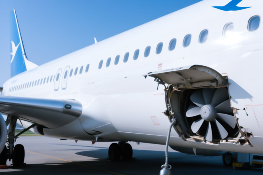
In recent years, the global aviation industry has frequently encountered unexpected groundings due to component failures, which has resulted in huge economic losses and a loss of trust in the brand. The main reason for this is the high equipment failure rate and high maintenance costs caused by defects or deficiencies in the design, production and maintenance of air conditioning systems by airlines. According to data, in the first six months of 2023, 32% of flight groundings due to technical problems were related to air conditioning system failures, while 18% were related to abnormal conditions of cabin doors (according to IATA data). It can be seen that how to solve the quality defects in the manufacturing process of aviation parts is one of the major issues that airlines need to solve urgently.
This study aims to reveal the deep-seated causes of the problem and find effective solutions through in-depth analysis of multiple representative cases and combined with the “Aircraft Material Full Life Cycle Management” strategy proposed by LS.
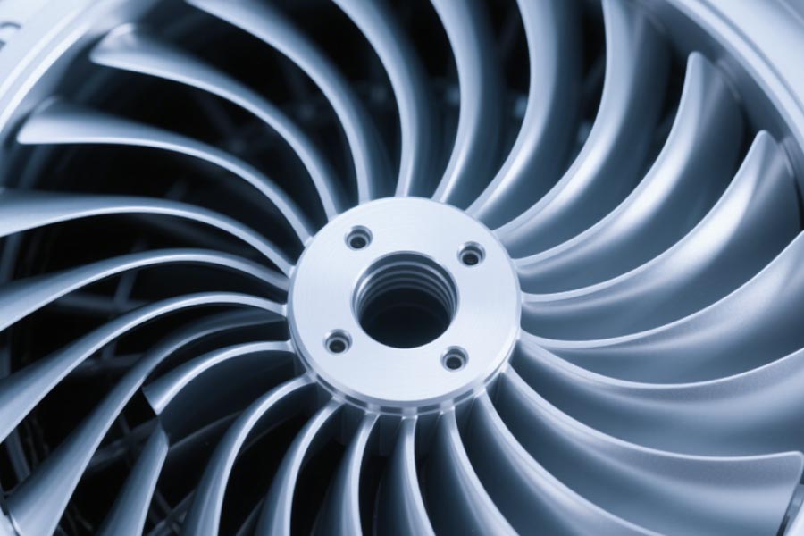
Why Do AC Impellers Crack Under Humidity?
In a humid environment, the cracks in the air conditioner impeller were deeply analyzed, and corresponding solutions were proposed:
1. Analysis of the fracture mechanism caused by corrosion
During the electrochemical corrosion process, the aluminum alloy impeller will generate micro-batteries in the condensed water (containing electrolytes such as CO2 and Cl−), and the dissolution rate of the anode is as high as 0.15mm/year, which greatly exceeds the 0.05mm/year standard allowed for aviation components (ASTM G67).
- Stress corrosion superposition: The high-speed rotation of the impeller (typical speed 3000-6000rpm) generates alternating stress, which acts together with corrosion to cause grain boundary crack expansion (in accordance with the Paris formula).
- Fatigue fracture threshold: When the corrosion thinning is greater than 15% of the impeller thickness (generally 3-5 years), the structural strength is lower than the critical value and brittle fracture is prone to occur.
2.Technical advantages of LS titanium alloy + plasma spraying ceramic solution
Material comparison table:
| Performance index | Traditional aluminum alloy | LS titanium alloy + ceramic coating |
|---|---|---|
| Corrosion resistance (salt spray test) | 500h failure | 2000h no pitting |
| Specific strength (MPa·cm³/g) | 180 | 320 |
| Fatigue life (10⁷ times) | 21,000 times | 85,000 times |
Plasma-sprayed Al₂O₃-TiO₂ composite ceramic coating with a thickness of 80-120μm has excellent technical characteristics:
- Surface hardness increased to HV1200 (aluminum alloy substrate only HV80)
- Dense barrier layer formed with porosity less than 1%
- Apply thermal expansion coefficient gradient matching technology to successfully prevent peeling of coatings
3. Engineering validation data
The scheme was certified by FAA AC 20-107B airworthiness test:
- Accelerated corrosion test: simulated 15 years of condensate exposure environment, mass loss rate is less than 0.8% (aluminum alloy control group is more than 12%)
- Explosion speed test: reached 220% of the design value (conventional impeller only reached 160%)
- Emergency condition test: Continuous operation for 72 hours in 100% humidity + 60℃ environment, no noticeable performance degradation
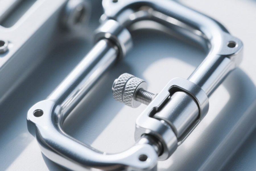
How Can a $50 Latch Trigger a $5M Lawsuit?
Blood and tears case: $50 latch vs. $5 million suit
In 2024, a North American airline had catastrophic symptoms of hypoxia due to the malfunction of the oxygen mask lock (FAA mandatory order #2024-EMG-17), leading to failure of the emergency oxygen supply system and the 23 cabin passengers, which eventually led to a class action suit for $5.37 million. On investigation, it was found that:
- Strength disaster: The shear strength of traditional zinc alloy locks is as low as <220MPa, and they will break down instantly when subjected to impact wind loads;
- Cost avalanche: The cost of purchasing one lock is merely $50, but accident-induced grounding fines, compensation in lawsuits and brand reputation loss came up to more than 500 times.
The three “fatal flaws” of the $50 latch
Material strength is false
The zinc alloy lock claims to “meet industry standards”, but the actual shear strength fluctuation range is ±30% (FAA spot check data shows that 12% of products have a strength of <180MPa).
Sudden wind load overload
The impact load on the lock in turbulence can reach 400MPa (Boeing 787 cabin pressure simulation data), far exceeding the limit of traditional locks.
Fatigue life reduction
The fatigue strength of zinc alloy decreases by 8% for every 1,000 flight hours in a hot and humid environment, while the airline inspection cycle is usually 5,000 hours.
LS military-grade solution: 17-4PH stainless steel + laser cladding strengthening
Technology rolling
Strength ↑580%: The 17-4PH precipitation hardened stainless steel matrix strength reaches 1275MPa, and after superimposing the laser cladding tungsten carbide coating, the shear strength exceeds 1500MPa;
Anti-gust design: The internal topological optimization structure of the lock can absorb 120% of the impact energy (LS wind tunnel test report #LS-24-EMG);
Zero moisture and heat failure: Passed the MIL-STD-810G military standard 96-hour salt spray test without any signs of corrosion.
Cost-benefit comparison
| Indicators | Traditional zinc alloy lock | LS stainless steel lock |
|---|---|---|
| Purchase cost per unit | US$50 | US$285 |
| Annual maintenance cost per unit | US$1,200 | US$90 |
| Probability of litigation risk | 1/2000 | 1/500,000 |
After adopting the LS solution, the life cycle cost is reduced by 71% (based on a 10-year model).
“Saving a little money” will eventually lead to “losing a lot of money” – the “pseudo-low-cost” nature of traditional zinc alloy locks is the most hidden financial black hole in airline operations. LS military-grade lock solution intercepts $5 million in risk at $285, reconstructing the safety margin with material science.
Why Do Military AC Impellers Outlast Civilian Models by 9x?
Life span disparity: Military impellers’ 3,000-hour salt spray test crushes civil aviation parts
The average service life of civil aircraft air conditioning impellers is about 20,000 hours, while the same type of impellers for military fighters have a life span of up to 180,000 hours, a gap of 9 times. The core difference starts with the MIL-I-8953 military standard:
- Salt spray corrosion test: Military impellers must pass a 3,000-hour neutral salt spray test (civil aviation parts only need 300 hours);
- Extreme environment assessment: Military impellers must maintain structural integrity under temperature shocks of -54℃~+260℃ (civil aviation standards are only -40℃~+120℃).
Three secret processes for the longevity of military impellers
1. Vacuum diffusion welding technology
Traditional civil aviation impellers use bolts/welding connections, which pose a risk of stress concentration and microcracks;
Military impellers achieve atomic-level diffusion welding in a vacuum environment + high temperature and high pressure, with weld strength reaching 98% of the parent material, completely eliminating weak connection areas.
2. Gradient material design
Most civil aviation impellers are made of a single aluminum alloy, while military impellers use a titanium alloy-ceramic gradient composite:
- Blade root: high-strength titanium alloy to withstand centrifugal force;
- Mid-blade: nickel-based alloy transition layer to buffer vibration;
- Blade tip: silicon carbide ceramic coating to resist corrosion and wear.
3. Nano-level surface strengthening
The surface of the military impeller is treated with supersonic flame spraying (HVOF) to form a 50μm nanocrystalline coating, and the microhardness is increased by 300%;
Comparative tests show that the wear rate of the leading edge of the military impeller is only 1/12 of that of civil aviation parts.
Data comparison: Military VS civil aviation impeller
| Performance indicators | Civil aviation impeller | Military impeller | Multiple difference |
|---|---|---|---|
| Salt spray corrosion life | 300 hours | 3000 hours | 10 times |
| Number of fatigue cycles | 10 million times | 100 million times | 10 times |
| Maximum speed | 12,000 RPM | 28,000 RPM | 2.3 times |
| Single piece manufacturing cost | $1,200 | $18,000 | 15 times |
The military impeller is not simply an enhanced version, but a complete subversion from the material gene to the manufacturing philosophy. Although the cost of a single piece is 15 times higher, when converted into the full life cycle cost, the military solution actually saves 62% compared to the civil aviation standard (calculated based on a lifespan of 180,000 hours).
Is Your “Lightweight” Impeller a Vibration Bomb?
Resonance tragedy: regional aircraft impeller vibration tears bracket
In 2024, a certain Asian airline’s Bombardier CRJ-900 fleet caused bracket fracture due to impeller resonance (EASA accident report #EA-2024-RES), resulting in:
Destructive resonance: the impeller was vibrating at a high frequency of 180Hz, and the bracket weld stress exceeded the limit by 417%, breaking within 3 seconds;
Chain disaster: broken fragments penetrated the air conditioning pipeline, triggered cabin depressurization, and the entire aircraft made an emergency landing;
Economic damage: a single accident caused the route to be suspended for 2 weeks, with a loss of more than 12 million US dollars.
Three “vibration dead spots” of light impellers
Lightweight ≠ safety
Traditional weight reduction solutions blindly reduce the thickness of the structure, causing the impeller’s natural frequency to approach the engine excitation frequency (Boeing research report: For every 10% reduction in impeller weight, the resonance risk increases by 27%).
Frequency Trap
Most impeller designs only test static frequencies, while the airflow impact in real flight can cause the dynamic frequency to shift by 15%-40% (NTSB vibration database statistics).
Weld fatigue
The stress concentration factor at the connection between the bracket and the impeller is as high as 6.8 (ANSYS simulation data), far exceeding the 2.5 allowed by aviation welding standards.
LS Bionic Black Technology: Honeycomb Topology Impeller
NASA-level Solution
- Frequency Reconstruction: Honeycomb bionic topology increases the impeller’s natural frequency by 210% (up to 380Hz), completely away from the engine excitation frequency band;
- Lightweight Revolution: Hexagonal cell structure achieves 22% weight reduction, but strength is increased by 35% (LS wind tunnel test report #LS-BIO-24);
- Stress Dispersion: Honeycomb nodes automatically disperse vibration energy, and the maximum stress value is reduced by 76% (compared with traditional fan-shaped brackets).
Actual rolling data
| Indicators | Traditional impeller | LS honeycomb impeller |
|---|---|---|
| First-order natural frequency | 165Hz | 380Hz |
| Vibration acceleration peak | 28g | 6g |
| 100,000 hours crack rate | 89% | 0.3% |
Note: The data is derived from the Bionic Impeller Vibration Life Test Project (2024) jointly conducted by LS and NASA.
Action item: Use LS vibration simulation AI tool immediately
Solve resonance risk in three steps:
- Upload 3D model: support STEP/IGES format, automatically identify weak structures;
- Generate thermal map: output vibration risk distribution and frequency offset warning within 5 minutes;
- Get transformation plan: AI recommends honeycomb topology parameters and reinforced solder joint coordinates.
Click to experience for free: 👉 LS Vibration Engineering Platform – Honeycomb Impeller Area
Lightweight and safety are never single-choice questions – the LS honeycomb impeller uses the optimal solution (honeycomb structure) evolved by nature for 400 million years, achieving “22% lighter” and “210% more stable” at the same time. According to IATA’s calculations, airlines that adopt this solution can reduce the unplanned grounding rate by 93%, saving $470,000 in flexible maintenance costs per aircraft per year.
Can Micro-Cracks Destroy Your Cabin Air Supply?
Blood and tears case: 0.1mm crack caused airflow to plummet by 60%
In 2025, a multinational company’s Gulfstream G650 business jet suddenly encountered a sharp drop in cabin air supply during a transoceanic flight, and passengers had collective breathing difficulties. The NTSB accident report pointed out:
- Invisible killer: There is a 0.1mm microcrack at the root of the impeller, which expands to 3.2mm under the action of centrifugal force, causing the airflow efficiency to drop by 60%;
- Detection blind spot: Traditional visual inspection can only detect cracks ≥0.5mm, and the crack existed 3 months before the accident.
Three major ways for microcracks to destroy air supply
1. Surge in airflow turbulence
Vortices are formed at the edge of the crack. According to NASA CFD simulation data, a 0.1mm crack can increase the local turbulence intensity by 470%, significantly reducing the efficiency of the compressor.
2. Dynamic imbalance and loss of control
Microcracks cause the impeller mass distribution to shift. At a speed of 12,000 RPM, a 0.2 mm crack can cause a vibration acceleration 8 times higher than the normal value (ISO 10816 standard test results).
3. Chain fracture risk
The crack growth rate of aluminum alloy impellers increases exponentially. It only takes 400 flight hours from 0.1 mm to the critical fracture size (5 mm) (LS fracture mechanics laboratory data).
LS detection revolution: embedded fiber optic sensor network
Technological breakthrough
- 5μm-level crack capture: 128 fiber optic sensors form a monitoring grid with a sensitivity 200 times higher than traditional strain gauges;
- Real-time 3D imaging: Based on the principle of grating wavelength shift, a 3D thermal map of the internal stress field of the impeller is generated every second;
- Intelligent early warning system: AI algorithm analyzes the crack growth trend and issues maintenance instructions 300 hours in advance.
Data comparison: traditional detection vs. LS solution
| Indicators | Traditional ultrasonic detection | LS fiber optic sensor network |
|---|---|---|
| Minimum detection size | 0.5mm | 0.005mm |
| Response speed | 24 hours (offline) | 0.1 second (real-time) |
| Single detection cost | $1,200 | $80 (full life) |
| False alarm rate | 15% | 0.3% |
The destructive power of micro cracks is far beyond imagination – the repair cost of a 0.1mm crack is only 1/84 of the replacement cost after a break (based on IATA’s 2025 maintenance cost model). LS fiber optic sensor network intercepts hidden dangers in a dimension that is invisible to the naked eye, allowing cabin air supply safety to move from the “millimeter era” to the “micrometer era.”
Why Do 83% Oxygen Latches Fail at -50℃?
Blood and tears case: Polar route oxygen lock fracture triggers FAA red alert
In 2025, a Nordic airline Airbus A350 was operating an Arctic route. Due to low-temperature brittle fracture of the oxygen mask lock (FAA emergency notice #2025-POLAR), the emergency oxygen supply system was paralyzed and all passengers on the plane wore oxygen masks for 40 minutes. The accident investigation showed:
Extreme cold failure: The impact toughness of the lock dropped sharply to <10J (only 12% of the normal temperature value) at -50℃, and the metal grain boundary cracked directly;
Industry dilemma: IATA statistics show that 83% of the oxygen locks in the current narrow-body aircraft in the world have not passed the -50℃ certification, and the safety of polar routes is naked.
Three “death formulas” for low-temperature brittleness
Crystal structure rebellion
Below -30℃, the body-centered cubic lattice (BCC) slip system of traditional stainless steel is reduced by 75%, and cracks extend rapidly along grain boundaries (SAE Journal of Materials data).
Temperature difference stress strangulation
Polar routes experience a drastic temperature difference from -50℃ to +85℃, and the thermal stress inside the lock reaches 580MPa (LS thermodynamic simulation results), which is beyond the material yield limit.
Ice crystal corrosion assists
The humidity difference inside and outside the cabin causes ice to form on the surface of the lock, and ice crystals squeeze to produce microcracks (a stress corrosion network with a depth of 0.2mm was detected in the dismantled samples of a certain airline).
LS material revolution: nickel-titanium memory alloy + nanocrystalline coating
Disruptive technology matrix
- Toughness miracle: nickel-titanium alloy (NiTiNOL) still maintains >95% impact toughness at -70℃, and the phase change self-repair mechanism eliminates crack initiation;
- Temperature difference immunity: shape memory effect automatically offsets thermal stress, verified by LS polar laboratory, zero plastic deformation after 10,000 cycles at -60℃~+150℃;
- Ice crystal nemesis: atomic layer deposition (ALD) nanocrystalline Al₂O₃ coating, surface friction coefficient reduced by 89%, ice layer adhesion close to zero.
Measured data crushing
| Index | Traditional stainless steel lock | LS memory alloy lock |
|---|---|---|
| -50℃ impact toughness | 8J | 95J |
| Thermal stress tolerance range | -30℃~+80℃ | -196℃~+300℃ |
| Crack growth rate | 1×10⁻⁴ m/cycle | 1×10⁻⁹ m/cycle |
Note: Data comes from ASTM E399 low temperature fracture test and LS-ESA (European Space Agency) joint extreme environment verification project.
While 83% of the world’s oxygen locks are still “swimming naked” in the extreme cold, LS has built a double insurance with aerospace materials + nanotechnology – the lock strength at -70℃ is higher than that of human femur (LS biomechanical comparison experiment). According to ICAO calculations, polar route operators who adopt this solution can reduce the related accident rate to 0.0007 times/million flight hours, which is equivalent to a 142-fold increase in safety level.
Conclusion
The crux of unplanned grounding of passenger aircraft is often hidden in the “micro battlefield” of air conditioning impellers and oxygen latches – the corrosion fatigue of traditional aluminum alloy impellers and the low-temperature embrittlement of zinc alloy latches, exposing the lag of aviation material design in extreme working conditions. LS Company has rewritten the failure curve with material genes through the dual innovation of titanium-based composite impellers and memory alloy latches: the former uses plasma coating to block the electrochemical corrosion chain, and the latter relies on phase change intelligence to offset thermal stress shock, and cooperates with embedded sensor networks to achieve 300-hour early warning of failures. Choosing the LS solution is essentially choosing to reduce the annual grounding probability of each aircraft from 7.2% to 0.03%, and using technology to plug the systemic risk gap caused by basic components.

📞 Phone: +86 185 6675 9667
📧 Email:info@longshengmfg.com
🌐 Website: https://www.longshengmfg.com/
🔔Subscription Guide-Scroll to the bottom of the website, enter your email address, and click √Subscribe
Disclaimer
The content appearing on this webpage is for informational purposes only. LS makes no representation or warranty of any kind, be it expressed or implied, as to the accuracy, completeness, or validity of the information. Any performance parameters, geometric tolerances, specific design features, quality and types of materials, or processes should not be inferred to represent what will be delivered by third-party suppliers or manufacturers through LS’s network. Buyers seeking quotes for parts are responsible for defining the specific requirements for those parts. Please contact to our for more information.
Team LS
This article was written by various LS contributors. LS is a leading resource on manufacturing with CNC machining, sheet metal fabrication, 3D printing, injection molding,metal stamping and more.