

With the continuous development and progress of technology, the machining dimensional accuracy, surface roughness and geometric tolerance of Superhard material shaped parts have a direct impact on the performance indicators of mechanism transmission, whether in the automotive, aerospace, medical equipment or industrial machinery industries.
They have unique shapes and complex CNC machining requirements, and traditional CNC machining methods often cannot meet their high-precision and high-quality machining needs. Therefore, the machining of irregular parts has become an important link in improving product quality and competitiveness.
In this article, we will detail how to solve the clamping problem by designing tensioning and positioning fixtures, using planar feature bottom tooth axial micro progressive milling and stress release deformation prevention technology, effectively solving the impact of various factors on accuracy and ensuring stable and reliable machining quality.
Characteristics of Superhard material
Superhard materials are a class of materials in particular that are harder than most materials on the market. They have excellent wear resistance and high cutting ability and are often used to process hard and brittle materials. Common superhard materials include diamond, cubic boron nitride and corundum ceramics.
Structural Analysis of Irregular Parts
The Superhard material special-shaped parts (see Figure 1) are free forgings. After quenching treatment before finishing, the hardness is up to 40~45HRC, which is difficult to machine.
Irregular parts have the characteristics of complex structure, high dimensional accuracy, and strict geometric tolerance requirements. The overall structure is irregular and irregular, with ribs, grooves, holes, steps, arcs, and angle features distributed in various spatial positions. The key control part of the groove bottom is 103mm relative to the benchmark hole spacing size, with a total length of 127mm and a minimum thickness of 10mm.
The dimensional accuracy and geometric tolerance of structural features in all directions relative to the reference hole and reference axis have strict requirements. After heat treatment, the deformation of the parts is significant, and the geometric accuracy requirements between holes and grooves, between holes and faces, and between faces are extremely strict.

Analysis of Difficulties in machining Irregular Parts
The parts are currently clamped on both sides of the flat part using a universal fixture (flat pliers) on a five axis machine tool (with a clamping allowance at the bottom of the clamping part), and processed using a cylindrical milling cutter radial cutting mode. Due to comprehensive factors such as cutting force, clamping force, cutting heat, and material stress release, it is difficult to ensure machining quality. Analyze the machining difficulties of this part in the following aspects.
1) Part clamping device
During the clamping process of parts, the clamped part of the workpiece needs to be positioned by the clamping force of a flat jaw pliers. The spatial position features maintain a relatively balanced state relative to the reference elements. In the case of small deformation of the part after clamping, the cutting process is completed and the accuracy requirements are met.
However, as soon as the clamping is released, the deformation of the clamping will be restored, which is difficult to avoid, resulting in the loss of the achieved accuracy and the drift of various geometric accuracies, making it impossible to meet the accuracy requirements.
2) cutting temperature
The quenching hardness of the parts is as high as 40-45HRC, and the cutting performance is poor. The key dimensions of the machined surface are with an accuracy of ≤ 0.02mm and a symmetry of ≤ 0.05mm. During the cutting process, it is easy to produce conditions such as tool sticking and cutting burrs at the tool tip.
The tool is prone to wear, and the surface size is prone to machining drift (drift ≥ 0.02mm), with a symmetry of ≥ 0.15mm, thereby damaging the geometric accuracy and surface roughness of the machined surface of the part. These comprehensive factors result in insufficient dimensional and geometric accuracy of the profile.
3) Material hardness
In the process of machining, due to the high Hardness, when the side edge of the cylindrical milling cutter is cutting, the radial cutting force causes the bending deformation of the workpiece and the vibration during machining. The direction of the radial cutting force and the vertical direction of the spindle produce tiny taper deformation, and the part produces elastic deformation after the force is released.
At the same time, the tool generates radial tension due to the influence of the tool helix angle, resulting in small elastic deformation and drift of various geometric accuracy. The longer the length to diameter ratio of the milling cutter suspension, the weaker the rigidity, resulting in feature size deviation exceeding the tolerance zone required by the process.
4) Metal removal margin
The metal removal rate of parts is relatively high, and uneven removal of allowance during the machining can lead to the destruction of the internal residual stress balance state of the parts, causing deformation of the parts. Especially at present, universal fixtures (flat pliers) are used for clamping and positioning.
The final step after the completion of part machining – removing the remaining clamping allowance at the bottom of the clamping part, a large amount of allowance is instantly removed, causing local release of residual stress, The dimensional and geometric tolerances of the parts lose their achieved accuracy, resulting in drift of various geometric accuracies.
Therefore, the existing process has defects and needs improvement.
CNC machining process solution for irregular parts
Based on the above technical analysis and ideas, the design technical solution is as follows.
1.Make tensioning and positioning tooling
There are many parts to be processed, with high requirements for dimensional and geometric accuracy. There is a strong correlation between the dimensions of each spatial structure. Therefore, on a five axis machining machine, the use of centralized processes, one-time clamping, and multi parts machining methods is easier to ensure dimensional requirements.
In the process of fixture design and production, the interference and collision factors of the tool, workpiece, and fixture during the stroke size and swing angle of the five axis machine tool are comprehensively considered.
1) Make a tensioning positioning fixture (see Figure 2), adopting the principle of one side, two pins positioning. Create a positioning reference plane and process threaded holes at the top of the fixture, and create internal threaded holes corresponding to the hole spacing and aperture at the clamping part at the bottom of the part. Connect and fasten with screws to achieve the tensioning positioning function of the workpiece and fixture.
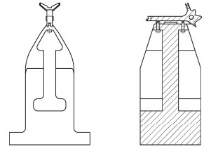
2) Design a space slot at the bottom of the process threaded hole on the process reference surface of the fixture to achieve the space for tightening the screws.
3) Design and manufacture the inclined surface of the tooling to ensure that there is no interference or collision between the cutting tool, workpiece, and tooling during the combination angle of the five axis machine tool swing head.
2.Machining grooves on the clamped part at the bottom of the part
To avoid the problem of stress release imbalance caused by the instantaneous removal of a large amount of surplus during the final step of removing the bottom margin after the completion of the machining of irregular parts, a groove (see Figure 3) is machined at the bottom process margin of the part before the quenching process to fully release the residual internal stress in the bottom clamping margin area, leaving only the position that meets the tension positioning requirements (as indicated by the arrow in Figure 3), You can process rounded corners at the bottom of the groove to avoid stress concentration at the sharp corners of the groove, which can lead to part fracture.

3.Micro Progressive Milling of Planes with Small Diameter Milling Cutter Axis
When precision machining planar features, the allowance allocated to each profile is very small and balanced. At this time, a small diameter short edge milling cutter is used for bottom tooth cutting. The milling cutter has good rigidity, small radial cutting force, and stable axial cutting force, which can effectively eliminate the influence of helical cutting force of the side edge milling cutter on the radial pulling force of the workpiece.
The use of micro progressive milling with bottom teeth can gradually release internal stress during the machining process of the part surface, making the changes in dimensional tolerances and geometric accuracy of the irregular part surface controllable. The cutting parameters of the milling cutter are shown in Table 1.
| Tool | Speed n/ (r/min) | Feed speed v/ (mm/min) | Feed rate f/ (mm/z) | Remark |
|---|---|---|---|---|
| 50mm disc milling cutter with end teeth | 1500±20 | 600±10 | <0.5 | Rough finish |
| 20mmRO.8mm end-tooth disc milling cutter | 5000 | 3000 | ≤0.1 | semi-finishing |
| 10mm carbide end mill | 5000 | 600 | 0.075-0.15 | semi-finishing |
| 10mm carbide end mill | 6000 | 1000 | ≤0.5 | semi-finishing |
| 10.1mm solid carbide drill bit | 2000 | 100 | 1 | Internal cooling work |
| 6.5mm center drill | 1500 | 50 | 1 | Work progress |
| 8mm solid carbide end mill | 6000 | 1500 | ≤0.025 | finishing |
| 10mm solid carbide ball end milling cutter | 6000 | 1500 | – | Residual height 0.001mm |
4.The process arrangement follows the principle of uniform removal of surplus
In order to control the deformation caused by uneven stress release of the material, the machining process of the remaining parts follows the principle of uniform removal of the residual amount except for the clamping part at the bottom.
1) Roughing and semi-finishing to remove the margin in order to improve the machining efficiency for the purpose of choosing the traditional machining method, clamping in the general fixture, through several times to remove the parts of the margin. The remaining margin is 3mm after rough machining and 0.3mm after semi-finishing.
2) Select the tightening positioning clamping method during finishing, with the help of the five-axis machine tool to achieve five-sided machining function, step by step to each profile for cutting, cutting allowance in turn decrease.
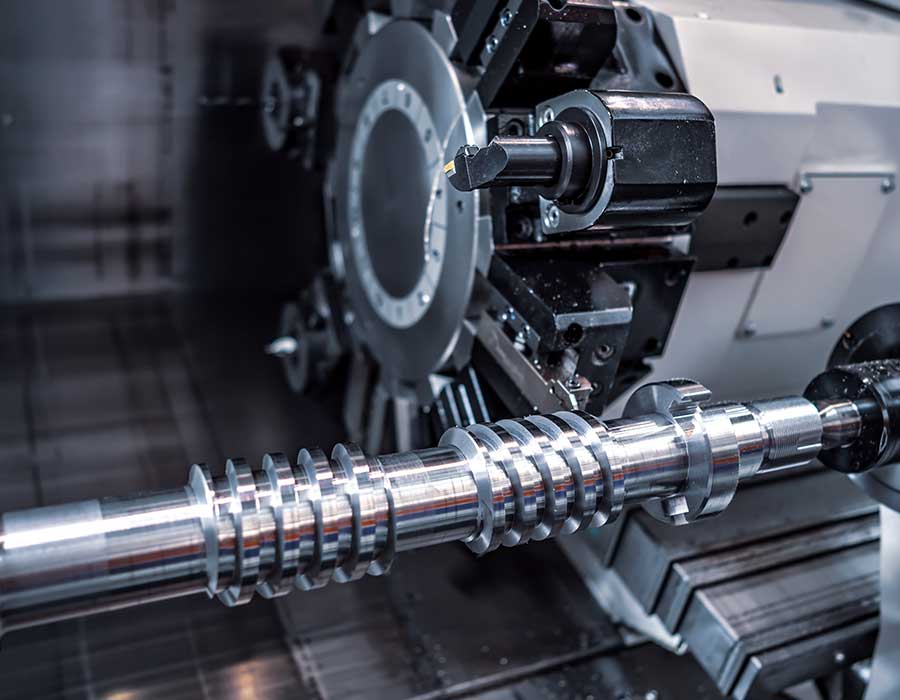
The five-axis machining of special-shaped parts is shown in Figure 4, and Figure 5 is the machining process flow.
Solutions for CNC machining of superhard materials
The innovation points of CNC machining process improvement for special-shaped parts of superhard materials are summarized as follows.
(1) Tension positioning technology based on part feature design
The tensioning positioning tool is changed from single-sided positioning and double-sided clamping to one-side tensioning positioning, avoiding the error caused by elastic deformation caused by clamping positioning, realizing the parts’ one-time clamping and multi-space parts machining , and ensuring the symmetry tolerance requirements of parts.
(2) Axial micro-progressive milling technology for planar feature bottom teeth
Machining plane features use small diameter short-edge milling cutter to eliminate the influence of side edge milling cutter helical cutting force on the workpiece radial pull. The micro progressive milling can release the internal stress of the parts and make the deformation of the special-shaped parts controllable.
(3) Stress release anti-deformation technology
The datum surface is reserved for clamping process convex, and the groove is cut on the process convex to fully release the internal stress of the special-shaped parts, so that the parts can be clamping and machining in the natural state. Under the comprehensive action of the above measures, the quality qualification rate of the special-shaped parts of the superhard material is ensured, which provides valuable experience for the machining of similar products.
conclusion
CNC machining technology is through pre-programmed instructions, the machining machine can be based on the design requirements of complex cutting, drilling, grinding and other machining operations. CNC machining technology can precisely control the cutting track and machining parameters, it can meet the precision machining needs of complex special-shaped parts, improve production efficiency and product quality.
FAQ
CNC machining of Superhard material special-shaped parts usually requires the use of advanced CNC machining equipment, such as drilling and milling composite machine tools and Electrical discharge machining machine tools. These devices have high precision, high stability and complex processing functions, and can meet the needs of Superhard material special-shaped parts machining.
The selection of proper CNC machining method depends on the specific requirements of Superhard material and parts. Common CNC machining methods include diamond wire cutting, laser cutting, and high-temperature and high-pressure cutting. Choosing the most suitable machining method according to different needs can improve efficiency and quality.