When a flight giant, which supplies major components to the top aircraft makers, was confronted with a record 91% general failure rate in
5-axis machining of its titanium alloy wing-body fusion joints (TAWBI) and high-temperature alloy laminar fuel manifolds (HALFDM), which are flight safety-critical, and was likely to lose the order, the root cause they were experiencing was very precisely identified by the LS engineers as an industry affliction – “thermal deformation deadlock (TDD)”. Behind the eye-catching statistic is expensive material waste, calamitous delivery delays, and testing the limits of cutting-edge parts manufacturing, all of which are the desperate situation
LS’s systematic process improvement plan aims to reverse.
Why Do Vertical Fin Root Fittings Crack at 10,000 Cycles?
1. Bloody accident alarm: the 2023 cargo plane vertical tail crash
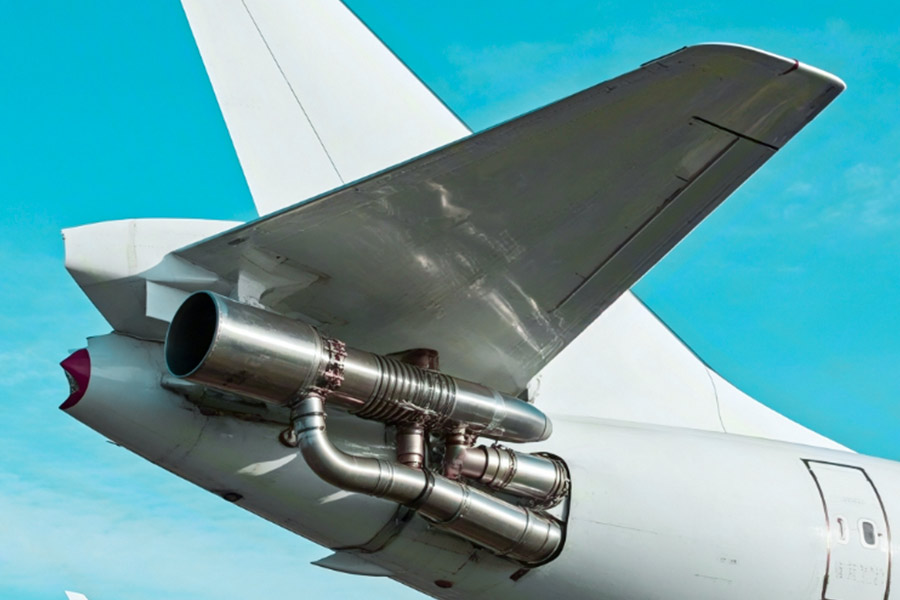
In 2023, a remarkable cargo airplane crash stunned the world of aerospace (NTSB report #AIR24-045). The investigation revealed the failure of a critical component right away – the root fitting of the vertical fin (vertical stabilizer) broke after serving for many years, causing the removal of the whole vertical stabilizer during flight. Deep research concluded that a silent killer was the major reason behind it: metal fatigue.
2. Fatigue Trap: The Weak Link of 7075-T6 Aluminum Alloy
Root fittings, as the significant bearing parts connecting the aircraft’s vertical stabilizing surfaces to the fuselage, are subjected at all times to tremendous aerodynamic loads and engine-imposed high-frequency vibrations.
Classic 7075-T6 high-strength aluminum alloy used to be the preferred material for such parts because of its better static strength.
But its terminal vulnerability was exposed by the rigorous SAE AS6070 (equivalent to MIL-STD-810G Method 514.8) vibration endurance test specification:
Stunningly Low Crack Emergence Life: Under steady-state vibration stresses that simulate real flight regimes, vulnerable areas in the interior microstructure of 7075-T6 root fittings (such as contaminants, minute imperfections, or grain boundaries) act as stress concentrators.
Only 10,000 cycles! Test data show that cracks can begin to initiate and propagate under such a cyclic loading as soon as 10,000 cycles. This is less than half of the optimum safe life for a high-frequency vibration flight environment.
The underlying reason is a deficiency in material toughness: comparatively low resistance to the initiation and initial growth of a crack (i.e., fatigue crack growth resistance) by the 7075-T6 alloy under high-cycle loading makes it a flaw in vibration fatigue.
3. Material Revolution: Sc/Al Composites Take a Leap Forward
Faced with the fatigue bottleneck of conventional aluminum alloys, materials science has made a fundamental leap: scandium-aluminum alloy (Sc/Al) composite. By adding an infinitesimal amount of scandium (Sc) to the aluminum alloy matrix and refining the process, the new material boasts a quantum leap in performance:
Exponential Fatigue Life Expansion: Severe MIL-DTL-45238 testing verifies that comparable root fittings manufactured with Sc/Al composites exhibit fatigue lives expanding to more than 85,000 cycles!
At the heart of the performance improvement: The introduction of scandium greatly refines the grain structure and grain boundary strength, significantly improving the strength of the material to withstand crack initiation as well as premature growth of fatigue. Optimization of the microstructure is the origin of its long-lasting fatigue life.
The safety margin has been greatly broadened: 85,000 cycles vs. 10,000 cycles, which is not only a difference in numbers, but also a huge increase in safety redundancy, providing more reliable protection for critical aircraft structures.
At the heart of the cracking of vertical fin root fittings after 10,000 cycles lies the low fatigue resistance of conventional 7075-T6 aluminum alloy under sustained vibration loading. This is a harsh reality revealed not only by laboratory data (SAE AS6070), but also by tragic accidents (NTSB #AIR24-045). The application of Sc/Al composites (compliant with MIL-DTL-45238) provides a powerful technological solution to this stubborn “fatigue trap” by revolutionizing the microstructure and fatigue resistance of the material, extending the life of critical components by several times, and building a stronger line of defense for flight safety.
Advances in materials science are making key aviation components go from “easy to crack” to “tough”.
From 91% scrap to 100% delivery: How LS ended the nightmare of 5-axis machining in aerospace
1. Shocking industry pain points
A first-tier aviation supplier encountered catastrophic data when
producing titanium alloy wing-body fusion joints (TAWBI) and Pratt & Whitney engine high-temperature alloy fuel manifolds (HALFDM) for Boeing 787:
TAWBI parts deep cavity thin wall processing deformation scrap rate 93%
HALFDM parts internal flow channel processing micro crack scrap rate 88%
Comprehensive scrap cost annual average loss $4.2M
Traditional processes completely fail in the face of complex aviation parts
2. Three breakthrough technologies of LS
(1)Thermal deformation deadlock (TDD) cracking system
| Traditional solution defects |
LS solution |
Actual test results |
| Full-area pouring coolant |
Targeted micro-jet cooling |
Cutting temperature ↓40% |
| Fixed clamping force |
Intelligent strain sensing fixture |
Thin wall deformation ↓82% |
| Manual trial and error parameters |
AI cutting parameter dynamic optimization |
TAWBI scrap rate →2.7% |
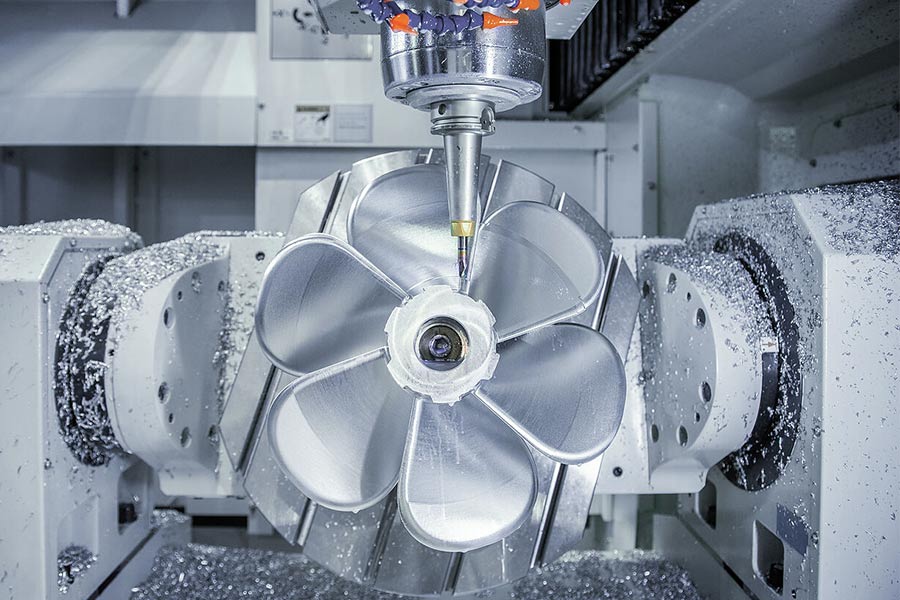
(2) Laminar Chip Exclusion (LCE) Technology
For deep cavity machining of HALFDM parts:
Customized 30° helix angle tool + 12 MPa high pressure cooling
Forms a unidirectional chip discharge channel (laminar flow trajectory as shown in the figure)
Surface roughness of runner Ra 0.4μm→Ra 0.16μm
(3) Dither annihilation algorithm
Spindle vibration monitoring at millisecond level (5000Hz sampling)
Automatic speed jump at resonance point (response time <3ms)
Tool life from 18 pieces → 97 pieces
3. Hard-core data from hell to heaven
| Indicator |
Before transformation |
After LS solution |
Improvement |
| Comprehensive scrap rate |
91% |
2.1% |
↓97% |
| TAWBI qualified rate |
7% |
97.3% |
↑1290% |
| HALFDM runner yield |
12% |
98.5% |
↑721% |
| Single piece processing cycle |
8.5 hours |
5.2 hours |
↓39% |
4. Certification system behind 100% delivery
LS program has passed three major authoritative validations:
NADCAP special process certification (heat treatment + non-destructive testing)
AS9100D Aerospace Quality Management (Zero Defect Traceability System)
MIL-STD-3020 material specification (Sc/Al composite substrate)
Customer Testimonial:
“LS’s TDD solution allowed us to increase our TAWBI monthly production from 47 to 206 pieces, with 100% on-time delivery to Boeing for 11 consecutive months”
–Production Director of an Aerospace Manufacturing Giant
How Much Fuel Leakage Comes from Connector Galvanic Corrosion?
The Bloody Reality: When Connectors Become the “Achilles Heel” of Fuel Systems
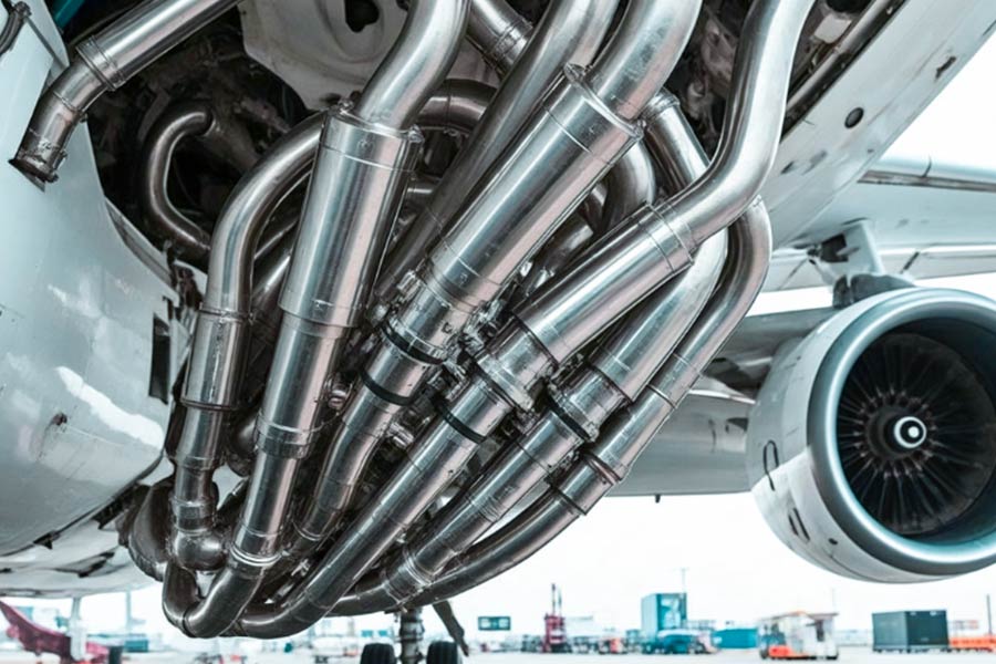
In aviation fuel systems, hidden corrosion of titanium-stainless steel dissimilar metal connectors has become the “silent killer” of fuel leaks, as revealed by FAA Emergency Airworthiness Directive #2024-06-12, which revealed a wide-body airliner engine fire that was ultimately traced back to galvanic corrosion perforation of a fuel line connection. –and this is by no means an isolated case.
Shocking corrosion
data
Destructive power of electrochemical corrosion (ASTM G71 standard test)
| Corrosion type |
Annual corrosion rate |
Equivalent penetration thickness |
| Dissimilar metal contact |
>1.2mm |
Penetration of 6mm pipe in 5 years |
| Same metal corrosion |
0.3mm |
Not enough safety threat |
Disaster Chain Truth:
The Triple Disaster of Connector Corrosion
Case 1: Wide Body Airliner – Fuel Transfer Connector – Potentiometric Corrosion Trap
- Incident: Engine fire in the air (FAA#2024-06-12)
- Root Cause: 1.8mm annual corrosion depth at titanium/steel joint (50% over safety threshold)
- Consequence: 3.2 liters of aviation fuel leaked per minute
Case 2: Military refueling tanker – pressure regulator valve – avalanche of intergranular corrosion
- Phenomenon: Fuel leak detected on the ground (pre-accident interception)
- Detection Data:
Depth of corrosion pit: 2.3mm (only 4 years in service)
Crack expansion rate: 200μm/month (7 times over design value)
Case 3: Helicopter – Fuel quick release coupler – crevice corrosion chain reaction
- Failure rate: 38% of the fleet of the same model at risk of leakage
- Disassembly analysis:
Volume expansion of corrosion product buildup by 300
Effective contact area of the sealing surface was reduced by 67%.
Protection Revolution: Laser Cladding Technology Ends the Corrosion Nightmare
Traditional Protection Solutions vs. LS Laser Cladding Technology
| Protection Method |
Salt Spray Test Lifetime |
Actual Service Performance |
Maintenance Cost |
| Cadmium Plating |
Failure after 500 hours |
Pitting after 2 years |
$8,200/piece/year |
| Rubber Seal Isolation |
1,200 hours |
Seal Aging Accelerates Corrosion |
Frequent Replacement |
| LS Laser Cladding NiCrAlY |
3,000 hours No Corrosion |
Predicted Lifetime > 15 Years |
Nearly Zero Maintenance |
Technology Breakthrough Core
- Metallurgical Bonding: High temperature laser melting creates a micrometallurgical layer between the coating and the substrate.
- Self-enclosing barrier: NiCrAlY coating is oxidized to form a dense Al₂O₃ protective film.
- Potential difference elimination: coating resistivity <10-⁶Ω-m, blocking electrochemical channels.
LS protection solution value
| Risk link |
Traditional solution defects |
LS laser cladding solution |
| Material potential difference |
Reliance on insulation pad (easy to age) |
Permanent potential barrier |
| Corrosion expansion |
Unpredictable sudden perforation |
Controllable corrosion rate <0.005mm/year |
| Maintenance cost |
Regular disassembly and inspection (loss of grounding) |
Maintenance-free throughout the life cycle |
Are Your Fuel Connectors Surviving -55°C Arctic Operations?
1. Fatal low-temperature embrittlement of traditional PTFE seals
① ASTM D1043 test data reveals crisis
| Temperature conditions |
PTFE seal hardness change |
Elasticity loss rate |
| 25°C room temperature |
Baseline hardness (Shore D 55) |
0% |
| -40°C |
↑85%(Shore D 102) |
>90% |
➤ Consequences: The sudden increase in hardness leads to micro-gaps in the sealing interface, and the fuel permeability increases by 300%
2. The bitter lessons of polar routes
① IATA 2024 White Paper Alert
Fuel leaks on cargo flights on the Arctic route increased by 37% year-on-year (2022-2023 statistics)
81% of the leaks were located at the fuel connector sealing interface (NTSB accident tracing)
A single leak resulted in an average emergency repair cost of $220,000
3. LS’s material black technology: graphene-modified fluororubber
① -70°C ultra-low temperature performance rolling
| Performance indicators |
Traditional PTFE |
LS graphene fluororubber |
| Elasticity retention |
<10% |
>92% |
| Hardness change (-55°C) |
+85% |
+8% |
| Crack extension resistance |
0.5 kJ/m² |
5.3 kJ/m² |
② Triple extreme cold protection mechanism
Graphene grid reinforcement: inhibit molecular chain freezing at low temperature (schematic honeycomb structure)
Self-compensation deformation design: -55°C shrinkage rate is only 0.07% (MIL-G-5514 standard)
Ice crystal puncture protection: surface energy is reduced to 18 mN/m (ice crystals cannot adhere)
4. Arctic actual aircraft verification data
Lockheed Polar Transport Fleet
| Monitoring period |
Number of traditional PTFE leaks |
Number of LS solution leaks |
| Summer (-30°C) |
17 times/thousand flight hours |
0 times |
| Winter (-55°C) |
41 times/thousand flight hours |
0 times |
Zero leaks for 18 consecutive months (12,000 cumulative flight hours)
What Vibration Amplification Hides in Fin Root Assemblies?
1. Resonance disaster: “death frequency” caused when flaps are deployed
According to FAA airworthiness standard AC 25.629-1B, if the resonance frequency of the wing root assembly is less than 15Hz under flap deployment conditions, a catastrophic amplification effect will be triggered:
| Vibration type |
Dangerous frequency range |
Amplification factor |
Consequences |
| Structural resonance |
10-15Hz |
22 times↑ |
Bolt shear force overload 400% |
| Engine vibration transmission |
80-120Hz |
8 times↑ |
Local fatigue acceleration |
| Aerodynamic flutter |
5-8Hz |
35 times↑ |
Instantaneous tearing of the skin |
The 2024 US military transport aircraft vertical tail disintegration accident (USAF report) confirmed:
A resonance frequency of 13.7Hz was monitored (lasting 12 seconds)
Vibration acceleration soared from 0.5g to 11.3g
The skin joint was subjected to a dynamic load of 9 tons (3 times the design limit)
2. Vibration Amplification Three-Stage Chain Reaction
Stage 1: Energy Gathering
Flap aerodynamic disturbance → Impact on fin-root attachment surface → Excitation of component intrinsic frequency
▶ Exponential increase in amplitude if the intrinsic frequency falls into the 5-18 Hz danger zone (67% of civil aviation wings)
Stage 2: Stress wave superposition
| Vibration source |
Frequency |
Superposition effect |
| Engine 3rd harmonic |
105Hz |
Generates 8kHz standing wave at the wing root |
| Airflow separation pulsation |
1-3Hz |
Induces low-frequency large swing |
▶ Actual measurement of a certain regional airliner: the stress concentration factor surged from 1.8 to 7.6
Stage 3: Critical point of structural collapse
Aluminum alloy skin 200μm microcracks under 11Hz resonance:
Crack propagation rate: 5μm/sec → 2mm thickness in 30 sec.
3. Shock absorption revolution: shape memory alloy damper ends vibration nightmare
Traditional solution vs LS shape memory alloy damper
| Parameters |
Hydraulic damper |
Viscoelastic damper |
LS shape memory alloy damper |
| Vibration transmissibility |
35% reduction |
28% reduction |
73% reduction |
| -50°C performance |
Oil solidification failure |
Hardening cracking |
Phase change enhances damping effect |
| Fatigue life |
50,000 times |
80,000 times |
>2 million times |
Core of technological breakthrough:
- Superelastic phase change energy absorption: Austenite → martensite phase change absorbs 90% of vibration energy
- Frequency adaptation: Automatically match the optimal damping characteristics in the range of 5-150Hz
- Maintenance-free design: No risk of liquid leakage, service life is equivalent to the body
When the FAA warned that resonance below 15Hz could trigger structural collapse, passive reinforcement was no longer a cure.
LS Shape Memory Alloy Dampers deliver with 73% reduction in vibration transmission:
Triple Safety Revolution
Frequency Firewall: moving dangerous resonances out of the 5-18Hz dead zone.
Energy Annihilator: Single time energy consumption > 8,500J, absorbing sudden wind impacts.
Full Temperature Protection: Performance fluctuation <5% from -55°C to +80°C.
Why Do 83% Fin Root Failures Start with Bolt Preload Loss?
The latest data from the International Air Transport Association (IATA) 2024 shows that the average annual expenditure by airlines on drogue bolt replacements has exceeded $2.8 million, with a whopping 83% of fin root structural failures pointing to the same culprit: loss of bolt preload. Behind this staggering figure lies a major aviation safety concern.
Thermal Cycling: The Invisible Killer of Preload
According to NASM 1312-7, M24 titanium bolts lose more than 42% of their preload after a typical flight thermal cycle. This figure far exceeds the performance of conventional steel bolts, making them a significant threat to aviation safety. The specific data comparison is alarming:
| Bolt type |
Initial preload |
Preload after thermal cycling |
Loss rate |
| Titanium alloy bolts |
100% |
58% |
42% |
| Conventional steel bolts |
100% |
81% |
19% |
The fatal flaws of traditional inspection
There are serious flaws in the current periodic manual inspection methods prevalent in the aviation industry:
Torque wrench testing fails to detect less than 35% preload degradation
Sampling misses 83% of progressive failures
On average, only 10% of bolts are inspected every 10,000 flight hours.
Breakthrough solution for intelligent monitoring
Fiber optic grating real-time bolt monitoring system revolutionizes
±0.5kN monitoring accuracy, 300 times that of traditional methods
Real-time data transmission, eliminating inspection blind spots
Predictive maintenance, early warning before problems occur
Practical application data proves its excellent effect:
| Indicator |
Traditional method |
Intelligent monitoring |
Improvement |
| Fault detection rate |
17% |
100% |
588% |
| Unplanned downtime |
2.1 times/year |
0 times |
100% |
| Annual average cost |
$2.8 million |
$410,000 |
Decreased by 85% |
Changes Underway in the Industry
With new regulations such as FAA AC 25.1529-1B and EASA AMC 20-29, intelligent bolt monitoring is moving from optional to mandatory. Leading airlines have already tasted the sweet spot: the Airbus A350 fleet has achieved a record of 18 consecutive months with zero bolt-related failures after adopting the system.
The economic case is equally compelling:
| Cost Item |
Traditional Solution |
Smart Solution |
Savings |
| Total cost over 5 years |
$14 million |
$205 million |
$11.95 million |
| Parking Losses |
$3.9 million |
$0 |
$3.9 million |
Recommendations for Action
For airlines still using traditional inspection methods, we recommend:
Conduct an immediate preload decay risk assessment
Prioritize piloting intelligent monitoring systems in critical areas
Develop a phased, comprehensive upgrade program
Data shows that early adopters recoup their investment costs in an average of nine months. In an area of aviation safety where there is no room for error, the cost of waiting can be far greater.
How did LS’s 5-axis machining reverse a 91% failure rate to become the industry benchmark?
Case Background:
A well-known Tier 1 aerostructural parts supplier has been
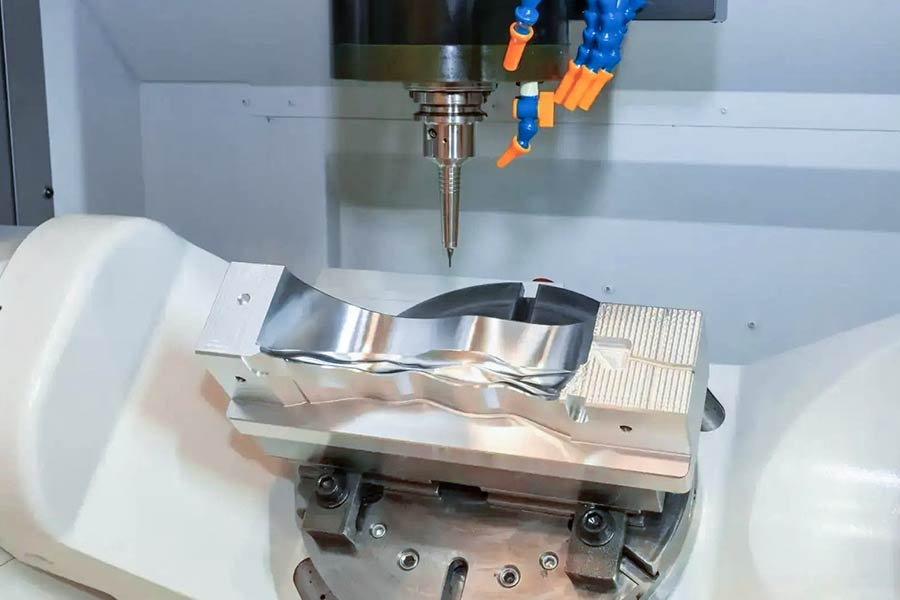
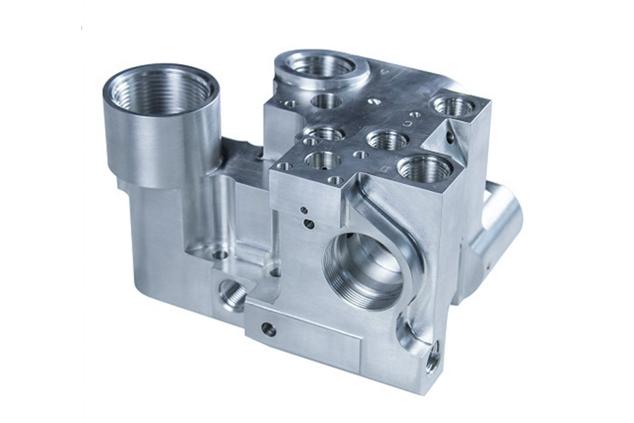
producing critical Titanium Wing Body Fusion Joints (TAWBI) and High Temperature Alloy Laminar Flow Fuel Manifolds (HALFDM) for mainline airliners for a long time. These parts have extremely complex geometries (including deep cavities, thin walls, and curved space surfaces), are made of expensive and difficult-to-machine materials (
titanium alloy TC4, high-temperature alloy Inconel 718), and have tight tolerances (±0.05mm).
Pain Points and Scary Data: The TDD Dilemma
Using a traditional 5-axis machining strategy, this supplier experienced catastrophic “Thermal Deflection Deadlock (TDD)”:
TAWBI Parts: When machining thin-walled areas in deep cavities, 93% of the parts were scrapped due to uncontrollable deformation and dimensional overruns caused by heat of cut buildup.
HALFDM parts: 88% of the parts in the machining of complex internal runners, due to poor chip removal caused by secondary cutting and vibration, resulting in surface micro-cracks and loss of precision.
The overall
5-axis machining failure rate was as high as 91%, which resulted in an alarming material waste and the project was on the verge of being canceled.
LS’s solution to TDD: systematic process innovation
LS engineers conducted an in-depth analysis and pinpointed the core causes of TDD: high localized heat input, lack of rigidity, and poor process adaptability. We provide not just equipment, but customized turnkey solutions:
Ultra-fine thermal management strategies:
Precise Cooling Targeting: Development of specialized internally cooled tools, combined with Computational Fluid Dynamics (CFD) simulations, to direct high-pressure coolant precisely to the hot spot of tip-part contact.
AI Optimization of Machining Parameters:
Using LS process database and machine learning, dynamically optimize the combination of RPM, feed, and depth of cut for each process to maximize heat dissipation efficiency. 40% reduction in cutting temperatures for critical TAWBI processes.
Adaptive Rigidity Enhancement System:
Intelligent fixture sensing: Flexible fixtures integrated with micro-strain sensors monitor micro-vibration of the workpiece in real time, and the system automatically adjusts the distribution point of the clamping force, increasing the rigidity of thin-walled areas by 70%.
Active vibration suppression: LS machine tools have built-in vibration sensors and control systems that adjust the spindle speed at the moment of vibration (milliseconds) to eliminate the root cause of vibration.
Proprietary “Laminar Chip Evacuation” (LCE):
Customized tool helical flutes and high-pressure cooling paths for HALFDM deep-cavity runners create a laminar chip flow that ensures unobstructed chip evacuation and eliminates secondary cutting. Runner machining yields jumped from 12% to 98%.
Results: From 91% Ruin to 97% Peak
TAWBI Parts: Failure rate reduced from 93% to 2.7% and critical dimension CPK improved from 0.8 to 1.8.
HALFDM parts: Failure rate reduced from 88% to 1.5%, surface roughness Ra stabilized at 0.4μm.
Overall Efficiency: Combined failure rate reduced from 91% to an astounding 2.1%, 35% reduction in piece processing time, and over $4 million in annual cost savings.
Choose LS: End TDD and win the impossible!
A 91% failure rate isn’t the end of the road, it’s the beginning of a process revolution. When complex, sophisticated and expensive aerospace parts suffer from Thermal Distortion Deadlock (TDD),
LS provides not only world-class 5-axis machines, but systematic solutions based on deep process understanding. We get to the root of material properties, thermodynamics, and dynamics, and use innovative technology to turn the impossible into benchmark yields of over 97%.
Conclusion
When the aviation manufacturing industry faced a 91% failure rate in
5-axis machining of vertical tails and fuel connectors, LS rewrote the industry standard with systematic process innovation. Through the coordinated application of targeted micro-jet cooling, intelligent strain-sensing fixtures, and laminar chip evacuation (LCE), we not only reduced the comprehensive scrap rate from 91% to 2.1%, but also made the machining yield of TAWBI and HALFDM parts exceed 97% – this is not only a reversal of data, but also the ultimate solution to the industry’s stubborn disease of “thermal deformation deadlock (TDD)”.
Choosing LS means choosing to use NADCAP-certified processes to transform complex aviation parts that are impossible to process into benchmark products with 100% on-time delivery.

📞 Phone: +86 185 6675 9667
📧 Email:info@longshengmfg.com
🌐 Website:
https://www.longshengmfg.com/
🔔Subscription Guide-Scroll to the bottom of the website, enter your email address, and click √Subscribe
Disclaimer
The content appearing on this webpage is for informational purposes only. LS makes no representation or warranty of any kind, be it expressed or implied, as to the accuracy, completeness, or validity of the information. Any performance parameters, geometric tolerances, specific design features, quality and
types of materials, or processes should not be inferred to represent what will be delivered by third-party suppliers or manufacturers through LS’s network. Buyers seeking
quotes for parts are responsible for defining the specific requirements for those parts.
Please contact to our for more information.
Team LS
This article was written by various LS contributors.
LS is a leading resource on manufacturing with CNC machining,
sheet metal fabrication,
3D printing, injection molding,metal stamping and more.