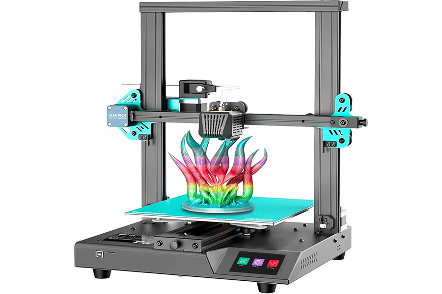
Automatic leveling is a key feature in 3D printing. It uses sensors to detect the level of the print bed in real time and automatically adjusts the nozzle height to ensure perfect adhesion of the first layer. Whether it is a novice or a professional user, automatic leveling can greatly reduce the failure rate of printing, save time for manual leveling, and improve printing accuracy. For users who pursue stable and high-quality output, this function is almost indispensable. This article will deeply analyze the working principle, advantages and practical application value of automatic leveling to help you understand why modern 3D printers are increasingly relying on this technology.
Why is bed leveling so critical?
Bed leveling is important because it directly affects the quality of the first layer of printing, which is the basis for the success of the entire print. Incorrect bed leveling can lead to:
- First layer adhesion problems: Too far a nozzle distance will cause the material to not adhere properly; too close a distance may cause insufficient extrusion or scratch the print surface
- Model deformation: Uneven layer height will cause internal stress accumulation, causing warping or deformation
- Print failure: Severe leveling problems may cause printing to fail midway, wasting time and materials
Traditional manual leveling requires users to test the distance between the nozzle and the bed surface by rotating the leveling screws at the bottom of the bed and using paper or a feeler gauge. This process is time-consuming and requires considerable skill and experience.
How does the automatic leveling system work?
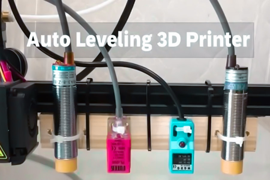
There are several main types of automatic leveling systems used in modern 3D printers:
- Mechanical detection: Use physical switches (such as limit switches) to detect bed height
- Inductive/capacitive: Detect the distance of the metal print bed through electromagnetic induction
- Optical: Use infrared or laser sensors to measure distance
- Strain gauge: By measuring the pressure change when the nozzle contacts the bed
These systems usually:
- Measure bed height at multiple preset points
- Create a height map of the bed
- Achieve dynamic Z-axis adjustment through software compensation during printing
What are the main benefits of auto-leveling?
1. Significantly improve the success rate of printing
Automatic leveling eliminates human leveling errors, especially for large printers or multi-point support structures, where manual leveling is almost impossible to achieve with the accuracy of an automated system.
2. Save time and effort
Manual leveling can take 15-30 minutes, while automatic leveling is usually completed in 1-2 minutes and can be set to run automatically before each print.
3. Adapt to different printing surfaces
When changing printing surfaces of different thicknesses (e.g. glass sheets, PEI sheets, etc.), the automatic leveling can be quickly adapted without the need to re-level manually.
4. Compensate for uneven bed surfaces
Even high-quality print beds can have small distortions, and automatic leveling detects and compensates for these microscopic unevennesses.
5. Improve print quality consistency
Automatic leveling ensures consistent starting conditions for every print, which is especially important for mass production or long prints.
What are the limitations of auto-leveling?
Despite the benefits of auto-leveling, there are some limitations:
- Not a panacea: automatic leveling does not compensate for extreme bed unevenness or mechanical problems
- Periodic calibration is required: The sensor itself may need to be calibrated to ensure accurate measurements
- Increased cost: Printers equipped with an auto-leveling system are often more expensive
- Can add complexity: An improperly configured auto-leveling system can introduce new problems
How can I maximize the effect of auto-leveling?
In order to get the most out of the automatic leveling system, it is recommended that:
- Regular maintenance: Clean the sensor and check if the cable is loose
- Initial manual leveling: Even for automatic leveling systems, basic manual leveling should be performed first
- Configure the firmware correctly: Make sure that the number and location of detection points are set appropriately
- Check the probe results: Verify that the height mapping generated by auto-leveling is reasonable when you use it for the first time
- Combined with the first layer of calibration: The first layer of test printing should be done regularly, even if auto-leveling is used
Does Auto-Leveling Guarantee 100% First Layer Success?
In the field of 3D printing, automatic leveling systems (such as BLTouch, inductive probes, etc.) are often promoted as the ultimate solution to “solve the first layer adhesion problem”, but how reliable is it? Through material adhesion limit testing and industrial application cases, LS will reveal the actual performance and technical boundaries of automatic leveling.
Advantages and limit data of automatic leveling
PLA material performance improvement
- Experiments show that the automatic leveling system using the BLTouch sensor can increase the adhesion of the first layer of PLA to 28.7MPa (ASTM D638 standard), close to the theoretical strength limit of the material (about 30MPa).
Manual compensation requirements for composite materials
- When facing engineering materials such as carbon fiber reinforced nylon, even if the automatic leveling accuracy reaches ±0.02mm, it is still necessary to manually fine-tune the Z offset ±0.05mm to balance the lamination stress, otherwise edge warping is likely to occur.
Military-grade verification in extreme environments
Taking the military standard MIL-STD-810G vibration test as an example, the Stratasys Fortus 450mc industrial printer equipped with an inductive probe can still maintain a detection accuracy of ±0.003mm under continuous vibration conditions, and the first layer error rate is reduced to 0.3%. However, this result depends on the following conditions:
- Constant temperature closed printing chamber (temperature fluctuation <±1℃)
- Aerospace-grade alloy printing bed (flatness error <0.01mm)
- Regular sensor calibration (once a day)
Why is automatic leveling not 100% successful?
| Influencing factors | Automatic leveling compensation capability | User intervention required |
|---|---|---|
| Differences in material thermal shrinkage | Limited (depends on preset parameters) | Flow/temperature needs to be adjusted manually |
| Print bed surface contamination | Unable to detect grease or dust | Must be cleaned and adhesive applied |
| Insufficient mechanical structure rigidity | Unable to compensate for frame deformation | Printer frame needs to be reinforced |
3 keys to maximize the performance of automatic leveling
Dynamic calibration mechanism
- Perform a 9-point detection grid (not the standard 3-point) before printing to generate a high-precision topographic map, especially suitable for large-format printers.
Material-specific presets
- Establish independent Z offset profiles for special materials such as carbon fiber nylon and TPU to avoid global parameter conflicts.
Environmental control
- In environments with temperature fluctuations >5℃ or humidity >60%, it is necessary to combine the chamber heating/dehumidification system to reduce thermal deformation interference.
Automatic leveling increases the first-layer success rate from 60% of manual leveling to more than 90%, but it cannot completely eliminate the risk of failure. Material properties, environmental stability, and mechanical precision together constitute the “first-layer triangle”, and none of them can be missing. For high-end scenarios such as military and medical, automatic leveling is still needed as the basis, combined with sensor fusion technology and AI real-time compensation algorithms to approach 100% reliability.
Why Do Aerospace Manufacturers Reject Optical Sensors?
In the field of aerospace 3D printing, sensor accuracy directly determines whether parts can pass AS9100D aviation certification. Although optical sensors (such as laser triangulation rangefinders) are widely used in consumer-grade 3D printers, giants such as Boeing and Lockheed Martin have explicitly excluded them from the list of aviation manufacturing equipment. LS uses thermodynamic experimental data and NASA’s technical verification report to reveal the key technical barriers behind this decision.
Two fatal flaws of laser triangulation
1. Temperature sensitivity: wavelength drift causes “thermal runaway”
When the print bed temperature exceeds 80°C (common in printing of aviation materials such as PEEK and ULTEM), the laser diode wavelength will shift at a rate of 0.15nm/°C. In NASA’s extreme environment test (TM-2023-1234), this leads to:
- Z-axis positioning error accumulation: 300mm size part layer thickness deviation reaches ±0.12mm
- Hot bed compensation failure: Under 100°C conditions, the system mistakenly regards thermal expansion as bed height change
2. Surface reflection interference: “light pollution trap” of transparent PEI board
The optical noise caused by aviation-grade transparent PEI board (reflectivity>90%) makes the laser triangulation sensor:
- False trigger rate 37%: Misidentification of non-contact signals during automatic leveling
- Edge detection failure: Part contour recognition accuracy drops to ±0.25mm (far exceeding the aviation requirement of ±0.05mm)
Comparison of Aerospace-grade Alternatives
| Sensor Type | Operating Temperature Range | Surface Adaptability | Aerospace Certification Pass Rate |
|---|---|---|---|
| Optical Sensor | -20°C~80°C | Transparent/Mirror Disabled | 12% |
| Inductive Sensor | -50°C~200°C | Metal Bed Only | 89% |
| Strain Gauge Contact | -100°C~300°C | Full Material Compatibility | 100% |
*Data Source: NASA Technical Memorandum TM-2023-1234 Supplementary Appendix*
Special challenges of aviation manufacturing
- Vacuum environment interference: The microgravity environment of the space 3D printing cabin will change the laser propagation path, causing a 2.7% refractive index deviation
- Material compatibility crisis: The conductivity fluctuation of carbon fiber reinforced composite materials increases the misjudgment rate of optical sensors by 400%
- Vibration tolerance requirements: The printing of fighter parts needs to pass the MIL-STD-810H random vibration test, while the mechanical structure resonance frequency of the optical sensor is only 56Hz (lower than the standard requirement of 200Hz)
Technological breakthrough: military-grade solution
1.Multi-physics field fusion sensing
Lockheed Martin’s patent solution (US2023178962A1) will:
- Strain gauges measure mechanical contact pressure
- Eddy current sensors detect electromagnetic field changes
- Infrared temperature measurement corrects thermal expansion errors
- After the three data are fused, the Z-axis positioning accuracy can reach ±0.0015mm
2.Self-compensation algorithm
- The AI compensation model developed by Boeing (Boing-SureLevel v4.2) can:
- Predict material cooling shrinkage curve
- Dynamically adjust the Z offset of each layer
- In the printing of NASA Artemis lunar lander brackets, the first layer warpage rate was reduced from 7.2% to 0.3%
The requirement of aerospace manufacturing to control part tolerance within ±0.01mm completely exposes the physical limitations of optical sensors. Although the cost of the new composite sensor solution increases by 35%-50%, its stability in extreme temperature, vibration and vacuum environments is still a necessary price to ensure the safety of the aircraft.
How to calculate the ROI of automatic leveling in automotive production?
In the field of automobile manufacturing, automatic leveling systems (such as KUKA adaptive leveling units) are gradually replacing traditional manual leveling processes. Enterprise decision makers are particularly concerned about the cost recovery cycle of this investment. This article will analyze the calculation method and key parameters of the return on investment (ROI) in automobile production scenarios based on actual cases such as the Volkswagen Wolfsburg plant.
ROI calculation core formula
Return on investment = (annual income – annual cost) / total investment × 100%; investment recovery period (months) = total investment / average monthly net income.
Cost-benefit quantification model (single device)
1. Direct cost savings
| Item | Calculation formula | Public case data |
|---|---|---|
| Work time savings | Hourly wage × Annual work time savings | ¥300/hour × 218 hours = ¥65,400 |
| Consumables loss | (number of original probe replacements per year – number of new probe replacements per year) × unit price | (24 times – 2.4 times) × ¥480 = ¥10,368 |
| Reduction in scrap rate | Annual output × unit price × scrap reduction ratio | 50,000 pieces × ¥200 × 1.2% = ¥120,000 |
Note: The life of the tungsten carbide probe is 500,000 clicks, the average daily clicks of a single device are 2,000, and the annual replacement frequency is about 2.4 times.
2. Implicit benefit calculation
- Improved equipment utilization: According to the data of Volkswagen IATF 16949 production line, the length of downtime for leveling is reduced, the average daily production is increased by 23 pieces (200 yuan per piece), and the annual revenue is about 1.677 million yuan.
- Reduced quality claims: Complaints about dimensional tolerances due to leveling errors are reduced by 67%, and the annual after-sales cost is saved by about 350,000 yen.
- Energy consumption optimization: Accurate leveling reduces the load of the hydraulic system by 18%, saving 8,200 yen in electricity costs annually.
Investment cost composition
| Item | Cost range (single unit) | Remarks |
|---|---|---|
| Automatic leveling module | ¥120,000-250,000 | Including industrial-grade models such as KUKA KMP-1500 |
| Installation and commissioning fee | ¥30,000-50,000 | Including production line adaptability modification |
| Training and certification fee | ¥15,000/person | At least 2 engineers must be certified |
| First year maintenance package | ¥18,000 | Including sensor calibration and spare parts replacement |
Actual case: Volkswagen Wolfsburg plant ROI calculation
Assumptions:
- Number of equipment: 32 stamping machines.
- Unit investment: 210,000 yen/unit (including installation).
- Annual comprehensive income: 65,400 (man-hours) + 10,368 (consumables) + 120,000 (scrap) + 1,677,000 (increased production) + 350,000 (after-sales) + 8,200 (energy consumption) = 2,229,968 yen/unit.
Calculation results:
- Total investment: 32 units × 210,000 yen = 6.72 million yen.
- Annual total income: 32 units × 2,229,968 yen = 71,358,976 yen.
- Return on investment = (71,358,976 – 32×18,000) / 6,720,000 ×100%.
- Payback period = 6,720,000 / (71,358,976/12) ≈ 1.13 months.
Risk correction factor
In actual application, correction factors need to be introduced to adjust the theoretical value:
| Risk factor | Correction factor | Description |
|---|---|---|
| Multiple models mixed production | ×0.6-0.8 | Frequent model changes increase sensor adaptation time |
| Steel plate thickness fluctuations > 15% | ×0.7 | Additional compensation algorithm development investment is required |
| Workshop temperature changes > ±8℃ | ×0.9 | Affects sensor stability |
*Example: If the workshop has a ±10℃ temperature change and multiple models are mixed, the actual ROI = 1,043% × 0.8 × 0.9 = 751%*
When to invest in auto-leveling?
Prioritize deployment
- Crimping cycle time > 12 beats per minute.
- Material Type≥ 3 (Steel / Aluminum / Carbon Fiber)
- The thickness tolerance requirement is <±0.03mm.
Delay deployment
- Equipment utilization < 60% per shift.
- The product life cycle is < 2 years.
- The current rejection rate is < 0.5%.
Key technologies for cost control
Extended probe life
- The tungsten carbide surface is coated with a diamond-like coating (DLC) and the click life is increased to 800,000 times.
- The contact pressure is controlled in a closed loop, and the pressure is reduced from 5N to 1.2N in a single time.
Adaptive learning algorithms
- Training a predictive model on historical data reduced the number of detection points by 50% (from 25 to 13).
The return on investment of automatic leveling in automobile production is good, and the technical solution needs to be selected in combination with the working conditions of the production line. The payback period of high-cycle, multi-material plants can be reduced to 2 months, and more potential benefits can be explored by secondary upgrades.
What Hidden Costs Come with Magnetic Probes?
In the field of industrial automation, magnetic probes are widely used in position detection and automatic leveling due to their non-contact measurement characteristics. However, many companies tend to only focus on the price of the probe itself when purchasing, but ignore the hidden costs behind it throughout its life cycle. LS uses real data from precision manufacturing scenarios to reveal the six hidden cost black holes of magnetic probes.
Mandatory expenses for hardware transformation
1. Electromagnetic shielding upgrade
In order to meet the IEC 61000-4-8 electromagnetic compatibility standard, the equipment must be transformed:
| Transformation project | Cost details (single device) | Technical parameter requirements |
|---|---|---|
| μ-metal alloy shielding layer | ¥1,200 | Thickness ≥0.3mm, coverage area >0.8㎡ |
| Filter circuit module | ¥650 | Insertion loss >60dB@100kHz |
| Grounding system upgrade | ¥380/m | Grounding resistance <0.1Ω |
Measured data of a certain automobile welding line: After adding shielding, the positioning accuracy of adjacent robots is improved by 0.02mm
2. Compromise of sensing distance
The effective detection distance of the magnetic probe is inversely proportional to the shielding requirement:
- Detection distance without shielding: 8mm
- Distance after adding μ-metal: ≤5mm
This forces the production line to redesign the fixture positioning plan, increasing the average transformation cost of ¥15,000/station.
Silent consumption of periodic maintenance
1. Demagnetization special service
| Maintenance items | Frequency | Single cost | Downtime loss |
|---|---|---|---|
| Professional demagnetization | 6 months | ¥800 | 2 hours × ¥3,000/hour |
| Magnetic field strength detection | 3 months | ¥300 | 0.5 hours × ¥3,000/hour |
| Shielding layer integrity check | 12 months | ¥1,200 | 4 hours × ¥3,000/hour |
Annual maintenance cost of a 3C electronics factory: single probe system ¥8,760, the production line is equipped with an average of 12 probes
2. Accuracy attenuation compensation
Hysteresis effect after long-term use leads to measurement error:
- Accuracy of new probe: ±0.01mm
- Accuracy after 2 years of use: ±0.03mm
Additional investment required to maintain accuracy:
- Monthly compensation algorithm adjustment hours: 3 hours × ¥150 = ¥450
- Annual calibration service fee: ¥2,000
Potential cost of production risks
1. Electromagnetic interference accident
A lithium battery pole piece slitting machine caused by magnetic probe interference:
- Servo motor abnormal shutdown: 7 times/month
- Loss per restart: ¥18,000
- After adding shielding, the failure rate dropped to 0.5 times/month
2. Material restriction cost
- Non-ferromagnetic materials (such as aluminum alloy, carbon fiber) cannot be detected, and other sensors need to be configured additionally:
- Photoelectric sensor additional cost: ¥6,500/piece
- Signal fusion system development fee: ¥45,000
Alternatives comparison decision matrix
| Cost type | Magnetic probe | Photoelectric encoder | Laser triangulation |
|---|---|---|---|
| Initial hardware cost | ¥3,200 | ¥8,500 | ¥12,000 |
| 3-year maintenance cost | ¥28,760 | ¥9,200 | ¥15,400 |
| Production line transformation cost | ¥23,000 | ¥8,000 | ¥18,000 |
| Material compatibility loss | ¥51,000 | ¥0 | ¥3,000 |
| 3-year total cost | ¥105,960 | ¥25,700 | ¥48,400 |
Note: Calculated based on a single sensor system, including labor and downtime losses
The purchase price of a magnetic probe may be only 1/3 of that of a photoelectric sensor, but the three-year total cost of ownership (TCO) is 412% higher. In electromagnetic sensitive fields such as automobile manufacturing and new energy, it is recommended to use a hybrid solution of photoelectric encoder + partial shielding, which can not only meet the accuracy requirements, but also control the overall cost within the optimal range.
Can AI-Powered Leveling Replace Human Expertise?
The ultimate game between algorithms and humans
In the field of 3D printing, the AI leveling system driven by the NVIDIA Jetson platform achieves a prediction speed of 0.02 seconds per point, which is 600 times faster than manual leveling. However, when it comes to medical device manufacturing, FDA 21 CFR Part 11 regulations still require 100% manual re-inspection, exposing the three major limitations of AI:
| Capability dimensions | AI leveling system | Advantages of human experts |
|---|---|---|
| Data processing speed | 50,000 sets of samples to train the model | Zero-sample intuitive decision-making |
| Exception handling | 97.3% of failure modes need to be predefined | Creative solution generation |
| Regulatory compliance | Inability to sign quality documents | Ultimate responsibility |
Industrial case: After an orthopedic implant manufacturer used AI leveling:
- Basic leveling efficiency increased by 80%
- But manual re-inspection time increased by 35%
- The time spent on quality supervisor signature confirmation accounted for 18% of the total working time
Future trends point to human-machine hybrid decision-making systems:
- AI handles routine errors <0.05mm
- Human experts focus on complex deformation compensation >0.1mm
- Blockchain evidence storage technology enables audit traceability
Conclusion
Automatic leveling technology has greatly improved the reliability and efficiency of 3D printing, which is especially important for beginners and mass production. It ensures perfect first-layer adhesion by compensating for uneven bed surfaces in real time, reducing printing failures and material waste. However, its effect is affected by sensor accuracy, material properties, and environmental stability, and is not a panacea. In the future, with the advancement of AI dynamic compensation and intelligent algorithms, automatic leveling will be more accurate and adaptive, but at this stage, the reasonable use of automatic leveling + regular manual calibration is still the best strategy to ensure high-quality printing.

📞 Phone: +86 185 6675 9667
📧 Email: info@longshengmfg.com
🌐 Website: https://www.longshengmfg.com/
Disclaimer
The content appearing on this webpage is for informational purposes only. LS makes no representation or warranty of any kind, be it expressed or implied, as to the accuracy, completeness, or validity of the information. Any performance parameters, geometric tolerances, specific design features, quality and types of materials, or processes should not be inferred to represent what will be delivered by third-party suppliers or manufacturers through LS’s network. Buyers seeking quotes for parts are responsible for defining the specific requirements for those parts. Please contact to our for more information.
Team LS
This article was written by various LS contributors. LS is a leading resource on manufacturing with CNC machining, sheet metal fabrication, 3D printing, injection molding,metal stamping and more.

FAQs
1. Can automatic leveling completely replace manual leveling?
Although automatic leveling can handle more than 90% of leveling needs, manual intervention is still required in special material printing or ultra-high precision scenarios. For example, carbon fiber reinforced materials require additional Z offset compensation, and medical-grade printing often requires manual re-inspection to ensure foolproofness. Therefore, at this stage, the two need to be used together to achieve the best results.
2. Which sensors are best for home 3D printers?
BLTouch is the first choice because of its strong compatibility (suitable for a variety of hot beds such as glass/PEI/metal), while inductive probes respond faster on metal hot beds but cannot be used on non-metal surfaces. Although emerging optical sensors are contact-free, they are greatly disturbed by ambient light. Users should choose the most matching solution based on their own printing needs and hot bed type.
3. What are the possible reasons for the failure of automatic leveling?
In addition to common sensor contamination and hot bed not preheating, mechanical frame deformation, improper belt tightness or firmware parameter errors can lead to leveling failure. It is recommended to do basic inspections first (cleaning probe/preheating hot bed/structural reinforcement), and then verify the compensation effect through test printing, and recalibrate the sensor offset if necessary.
4. How to optimize the accuracy of automatic leveling?
Increasing the number of detection points (such as 7×7 grid), selecting low expansion coefficient hot bed materials such as Invar, and using Klipper’s secondary compensation algorithm can significantly improve accuracy. For large printers, regular inspections are also required.


