

CNC milling is a high-precision and high-efficiency machining method widely used in the manufacturing industry. Excellent part structure design plays a crucial role in CNC milling. A reasonable part structure can reduce machining difficulty, improve production efficiency, and ensure the quality of the final product.
This article will introduce you to the key guidelines for the structural design of CNC milling parts. By designing the part structure reasonably, comprehensive improvement in machining efficiency and quality can be achieved, helping you achieve better results in the field of CNC milling.
CNC milling machining method
Before exploring CNC milling part design in depth, it is essential to have an in-depth understanding of CNC milling machining methods. Through a comprehensive understanding of CNC milling, we will be able to better understand and apply the relevant points of part design.
1) Milling basic machining
Including: surface milling, groove milling, side milling, copying milling.
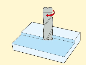
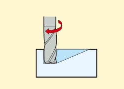
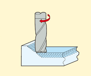
1.Flat milling:
The end teeth of the cutting tool mesh to form a flat surface.
Tool engagement: AP is small and AE is large.
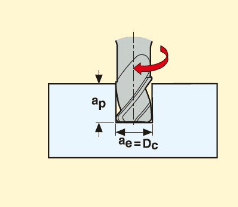
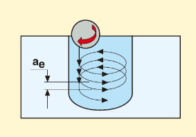
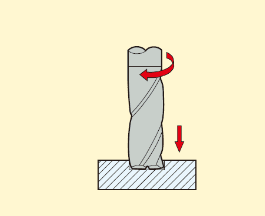
2.Milling groove:
Machining with fully engaged tool diameter,
Ae is equal to Dc and Ap is up to 1,5 times that of Dc. Dc depends on the machining strategy used.
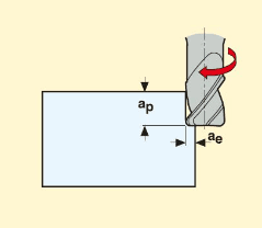
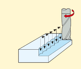
3.Side milling:
Machining is carried out through the meshing of the tool side.
Ap is large and Ae is small.
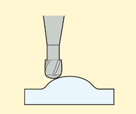
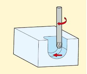
4.Copying milling:
Machining of the ball part of the tool meshing.
Ap and Ae are small.
2) Advanced milling machining
Including: slope milling, thread interpolation, cycloidal milling, push-pull copy milling, interpolation milling, contour milling, drilling.
1.Slope milling:
The cavity is milled at an Angle in the Z-axis direction.
2.Spiral interpolation ramp milling:
At the same time of Z-axis slope milling, the tool is milling the cavity with circular motion.

3.Cycloidal machining:
Make a partial circular motion in the X or Y axis, grooving by using a side mill. (Turn milling groove into side milling).
4.Push-pull copying milling:
Machining a 3D profile by copying up and down the profile.
5.Insert Milling:
Use the (Z) shaft to drill a deep groove.
6.Contour milling:
A surface is machined by a small amount of drilling or slope milling on the Z axis, and then the cavity is milled by moving along the X and Y axes.
7.Drilling:
Move along the Z axis to process a hole.
Definition of CNC milling machining
CNC milling machining is to convert the designed CAD drawings into machine instructions, and the CNC control system accurately controls the tool to cut materials on the workpiece surface, so as to obtain the required part shape.
Ordinary machining
It is a general-purpose machining strategy. The ratio of cutting width to cutting depth can vary depending on the type of process.
1) Tool characteristics: The tool has a relatively long cutting edge and a smaller core diameter, with no high requirements for accuracy.
2) Machine tool requirements: No special requirements.
3) Application field: With basic CNC technology, advanced machining methods with high difficulty are not feasible; The metal removal rate can only reach an average level; The application fields typically include small batch sizes and a wide range of materials.
High speed machining
It is a machining strategy that combines small radial cutting depth, high cutting speed, and feed speed; According to the adopted method, high material removal rate and low Ra value can be achieved. The typical characteristics of this strategy are low cutting force, less heat transferred to the tool and workpiece, reduced formation of burrs, and high dimensional accuracy of the workpiece; Under high-speed machining, using faster cutting speeds than regular machining can achieve high metal removal rates and good surface roughness.
1) Tool characteristics: Stable (larger core diameter and shorter cutting length), clear and well formed chip holding space, conducive to good chip removal and coating.
2) Machine tool requirements: high-speed CNC control, high speed, and fast feed speed of the workbench.
3) Application field: Hardened steel (48-62 HRC) in the mold industry for semi precision machining and precision machining, with short delivery time. When using the correct cutting tools and advanced machining methods, this technology can also be applied to many other materials.
High performance machining
It is a machining strategy that can achieve a very high metal removal rate. The typical feature of this strategy is that the cutting width is twice that of Dc, and the cutting depth is 1-1.5 times that of Dc, depending on the workpiece material; Under high-performance machining, using a machining method with much higher chip load than ordinary machining can achieve extremely high metal removal rates.
1) Tool characteristics: A specially developed chip holding structure on the chip removal groove of the tool, with a 45 ° small flat surface or tip arc for protection, a particularly smooth chip holding space, plating, with or without side fixing handles.
2) Machine tool requirements: High stability, high power requirements, and high rigidity clamping system.
3) Application field: In large-scale production and machining , production efficiency is a key indicator, or it is required for single piece product machining with high metal removal rate.
High feed machining
It is a high feed machining strategy that combines full edge cutting with small cutting depth for the entire tool diameter. Under high feed rate machining, it is possible to achieve high metal removal rate and good surface roughness by using a faster feed rate than regular machining.
1) Tool characteristics: specially developed tool tip, extremely short cutting length, and coating.
2) Machine tool requirements: high stability, high possibility of feeding speed.
3) Application field: From soft steel to hardened steel, titanium alloy and stainless steel, it is very good as a pre machining before high-speed machining, and can also be used for deep cavity machining. One of the advantages of this technology is that it is very convenient for users to achieve simple, safe, and fast programming in CAM. With the so-called Contour line milling strategy, complex shapes can be easily programmed without rich programming experience.
Microfabrication
It is a machining strategy that uses extremely small tool diameters.
1) Tool characteristics: diameter range from Ø 0.1 to 2.0mm, short cutting length, wide range of cylindrical reduction, high accuracy, and coating.
2) Machine tool requirements: high spindle accuracy, high speed, CNC, and thermal stability to prevent spindle elongation.
3) Application field: machining various cavities on a variety of materials.
Basic principles of CNC milling parts design
The size of the tool used in milling is a key factor to consider when designing a part.
When designing, it is always necessary to consider whether the new feature has a tool that can process the feature.
Fewer clamping times not only reduce machining time, but also improve accuracy. Reduce machining time.
Reducing the amount of material removed can save machining time and cost.
1.Thread hole design
The internal thread can be machined with a tap or thread milling cutter. The tap can be used for tapping M2 and above threads. CNC threading tools can be used to process the smallest M6 thread.
Thread length
| Thread length | Minimum value | Recommended value |
| mm | 1.5x diameter | 3x diameter |
Most of the load applied to the thread is borne by a few turns of thread (up to 1.5 times the diameter) beginning at the thread opening. Therefore, threads that exceed 3 times the nominal diameter are generally not required. For threads in blind holes machled with taps (i.e., all threads less than M6), add an unthreaded length equal to 3 times the pitch at the bottom of the hole (the lead-in section present at the bottom of the tap).
When milled threads (i.e., threads greater than M6) are available, the hole can be threaded over its entire length (designed retracting slots).
Avoid deep tapping
In order to obtain accurate and precise results, avoiding deep tapping is crucial in CNC machining design.
The longer the tapping depth, the greater the risk of vibration and offset during operation, resulting in defects in the final product.
Threads that exceed 3 times their diameter are considered deep and may pose a risk. However, in many cases, even thread lengths with a diameter of 1.5 times can provide sufficient thread engagement to eliminate the need for deep tapping at all.
Using a deep tap increases the risk of tool breakage, thread defects, and reduced accuracy, making it an undesirable aspect of the design.
2.Aperture and hole depth design
Holes can be machined using a drill or a milling cutter.
The size of the drill is standardized (metric and imperial units).
Reamers and boring cutters are used to finish holes that require tight tolerances.

For high-precision holes with diameters less than 20mm, standard diameters are recommended. Holes of non-standard diameter must be machined with milling cutter. In this case, the cavity depth limit should be kept within and the recommended maximum depth value should be used.
| Minimum aperture | Suggested value | Feasible value |
| mm | 2.5 | 0.05 |
In most cases cavities and holes can be precisely machined using tools with a diameter of less than 2.5 mm. Anything below this limit is considered micromachining.
Micromachining requires specialized tools (micro-drills) and expertise, so the advice is to avoid these problems unless absolutely necessary.
In CNC machining, there is no special preference between through holes and blind holes. On non-CNC milling machines, through hole machining is often simpler than blind hole machining.
Hole depth
| Hole depth | Recommended | Feasible (strict) |
| Reference value | 4x diameter | 40x diameter |
Design holes as short as necessary.
Deep hole drilling can work very deep holes, but this requires additional systems and tools.
3.Parts wall thin design
When metal is used for milling or CNC machining, thin walls increase chatter, which affects the precision of the machining process and the surface finish of the part. For plastics, thin walls can cause warping and softening.
Therefore, every effort should be made to avoid designing thin-walled parts. In practice, a minimum wall thickness of about 0.8 mm (metal) and 1.5 mm (plastic) for metals is possible.

Note: In order to avoid misdirection, it is necessary to keep the wall thickness of the metal parts above 1.52mm under normal circumstances if not necessary. Similarly, plastic parts should be more than 2mm.
It is possible to achieve a thinner cross-section without significant risk, but this needs to be assessed on a case-by-case basis.
4.Flat bottom hole design
Machining flat bottom holes requires more expensive machining methods and often creates problems in subsequent machining, such as reaming. Avoid creating flat flat blind holes, especially small holes, and instead use a standard twist drill to create tapered bottom holes. The cone Angle is usually 118°.
It should be emphasized that the model should keep the cone corner bottom hole design when designing, which is not difficult to operate, rather than throwing the problem to the manufacturing.

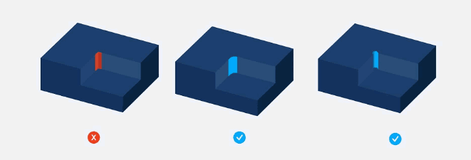
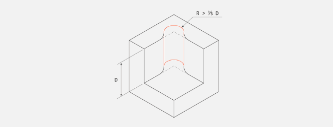
5.Internal bevel design
Because all milling cutter heads rotate in a circular rotation body, it is impossible to achieve internal beveling. Instead, the milling cutter leaves an unworked area (corner) with the same radius as the tool.
Internal chamfering or unchamfered internal grooves can be machined using alternative methods such as EDM, but these methods are often expensive.
The size of the tool used in milling is a key factor to consider when designing a part.
Larger tools remove more material in a single machining, reducing machining time and costs. An additional trick is to make the fillet slightly larger than the radius of the end mill.
A corner radius that is 0.1 larger than the standard tool diameter will create a smoother cutting path and produce a finer finish on the machined part.
In order to take full advantage of the larger tool, please design the maximum radius of the inside corner, preferably greater than 0.8mm.
In addition to micro machining, if the space is sufficient, the corner radius R is greater than 3mm, and keeping the tool as large as possible can improve efficiency and tool stability.
| Radius value | Recommended value |
| Internal R | At least 1/3 depth |
If the design of the structure requires straight corners, you can use the flexible design below. It should be pointed out that using a drill instead of a milling cutter at the corner can obtain a smaller corner and the required depth.
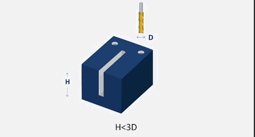
6.Deep tank design
Deep and narrow slots must be machined with longer tools, which are more likely to break and may also cause tool vibration or machine tool vibration.
In addition, machining a deep groove requires several processes, which increases machining time and manufacturing costs.
Avoid designing parts with deep grooves whenever possible. If this cannot be avoided, engineers and designers should reduce its depth or increase the cross-sectional area of the slot as much as possible.

In general, the depth of the groove should not exceed 3 times the diameter of the tool used. For example, when using a 6mm tool, the depth of the groove must not exceed 18mm.
Engineers may need to adjust this number depending on the materials used and the tools available.
After completing the structure design of CNC milling parts, simulation and testing are necessary steps. The feasibility and accuracy of the design are verified by computer simulation and physical test. Early detection of potential problems and modification will help avoid unnecessary waste and delays in subsequent production.
conclusion
CNC milling part structural design is a highly complex process, but following the above guidelines can help you optimize your manufacturing process and improve product quality. Reasonable optimization of geometry, addition of fillet and chamfer will have a positive impact on the final part performance.
FAQ
The cost of controlling the structural design of CNC milling parts has several aspects. First of all, reasonable reduction of material waste and machining difficulty helps to reduce production costs. Secondly, optimize the machining path and sequence, improve machining efficiency, save machining time and energy consumption. Finally, simulations and tests are carried out to detect potential problems early and avoid additional costs associated with subsequent machining .
In the structural design of CNC milling parts, it is very important to choose the right material. Materials should be selected according to the function, use and technical requirements of the parts. Common materials include metals (such as aluminum, steel, copper, etc.) and engineering plastics.
CNC milling is an automated machining technology that uses computer-controlled CNC milling machines to process parts. This technology uses a tool to rotate and move on the workpiece, thereby cutting, carving, and machining the workpiece in a high-precision manner to achieve predetermined shapes and dimensions.