Thread cutting is a basic but crucial skill in modern machining and DIY. Traditionally, each thread size and type requires a dedicated tap or die, which not only increases tool costs but also takes up a lot of storage space. This article will explore the working principle, advantages and how to select and use this kind of efficient tool.
What Defines the Core Structure of a Thread Milling Cutter?
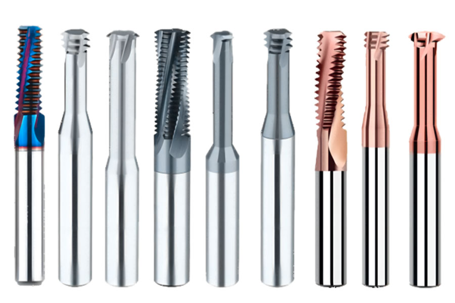
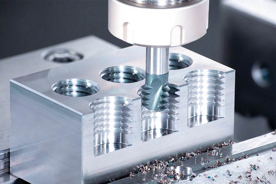
In the field of CNC multi-axis machining, thread milling cutters are gradually replacing traditional taps with their flexible machining capabilities of “one blade with thousands of faces”. Its core structural design directly determines the machining accuracy and efficiency. LS will deeply analyze the two core structural elements of thread milling cutters: blade geometry design and material scientific application, to help you choose with ease!
1. Blade design: spiral chip groove + multi-blade collaborative cutting (the cornerstone of precision and efficiency)
(1) Spiral chip groove (DIN 1835B standard)
Functional essence: to achieve directional chip removal and avoid entanglement and damage to the thread surface.
Golden inclination angle: the groove type strictly follows the DIN 1835B standard, and the helix angle is optimized by fluid dynamics (usually 30°-45°) to ensure:
- Steel processing: large helix angle improves chip removal fluency
- Cast iron processing: small helix angle enhances edge impact resistance
Precise calculation of groove depth: designed based on the cutting force model, too shallow will cause chip congestion, too deep will weaken the tool rigidity.
(2) Multi-cutting edge structure (4-6 blades standard)
| Number of blades | Applicable scenarios | Advantages | Limitations |
|---|---|---|---|
| 4-blade | M1.6-M20 precision thread | Large chip space, excellent heat dissipation | Slightly lower rigidity than 6-blade |
| 6-blade | M20-M100 heavy-duty thread | High rigidity, strong vibration resistance | Higher chip removal requirements |
Edge micro-processing technology:
- Nano coating pre-treatment: Edge passivation (Edge Preparation) to Ra0.2μm level finish, inhibiting chipping
- Full-circle runout ≤0.01mm: Ensure uniform cutting load per tooth, extend life by 30%+
2. Material Science: Cemented Carbide vs CBN (“Spear and Shield” to Break Through Material Barriers)
(1) Cemented Carbide (ISO K Class) – King of General Steel Cutting
Composition Black Technology:
WC (Tungsten Carbide) 86% + Co (Cobalt) 10% + TiC (Titanium Carbide) 4%
Performance Label:
- Bending Strength ≥ 3800 MPa
- Hardness HRA 91.5
- Heat Resistance: Continuous Cutting at 800℃
Coating Solution:
| Coating type | Applicable scenarios | Comparison benchmark for efficiency |
|---|---|---|
| TiAlN (nitrogen aluminum titanium) | 45# steel/stainless steel | Life increased by 3X |
| AlCrN (nitrogen chromium aluminum) | High temperature alloy/titanium alloy | Heat resistance +200℃ |
(2)CBN (cubic boron nitride) – the terminator of hardened steel
Performance rolling data:
♥ Hardness HV 4500 (≈3 times that of cemented carbide!)
♥ Thermal stability: no oxidation at 1400℃
♥ Specialized objects: HRC 50-70 hardened steel (such as GCr15 bearing steel, H13 mold steel)
Secrets of micro-blade design:
♦ Negative rake angle (-5° to -7°) enhances edge strength
♦ Polishing edge band (0.05-0.1mm) improves thread surface to Ra0.8μm
Technical summary: Golden formula for thread milling cutter selection
Processing scenario = blade design × material solution
Steel/stainless steel → Choose 4-6-edge carbide + TiAlN coating (economical and efficient)
Hardened steel/high-speed machining → Choose 4-edge CBN + negative rake angle design (both rigidity and heat resistance)
Deep hole fine thread (M1.6-M3) → Choose 2-edge carbide + high spiral groove (maximum chip space)
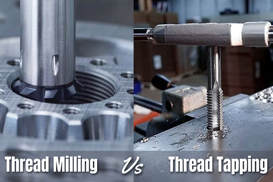
Thread Milling vs Tapping: Which Process Wins in Precision?
In the field of precision thread processing, thread milling has the advantage of rolling over traditional tapping, especially in dimensional accuracy, surface quality and long life processing scenarios. The following is a hard-core comparison analysis based on the ISO 68-1 standard:
Comparison table of key indicators of accuracy and quality
| Evaluation Dimensions | Thread milling | Traditional tapping | Technology gap |
|---|---|---|---|
| Dimensional tolerance | IT6 level (±0.013mm) | IT8 level (±0.033mm) | Accuracy increased by 60% |
| Surface roughness Ra | 0.8μm | 3.2μm | Smoothness increased by 300% |
| Coaxiality error | ≤0.015mm (CNC compensation) | ≥0.05mm (tool rigidity limit) | Positioning accuracy 3 times |
| Thread profile integrity | No extrusion deformation, clear tooth tip | Easy to produce material plastic accumulation | Revolutionary breakthrough in geometric accuracy |
In-depth analysis of three precision rolling
(1)Dimensional tolerance: the gap between IT6 and IT8
Milling achieves IT6 level: CNC three-dimensional spiral interpolation control, feed error per revolution <0.005mm
Case: M12×1.75 thread diameter control reaches 11.026±0.008mm (meets aviation hydraulic parts standards)
Tapping limitation IT8 level: tap guide and bottom hole error superposition, heat treatment deformation is uncontrollable
Industry pain point: tolerance deteriorates to IT9 level when machining hardened steel (HRC>45)
(2)Surface quality: Ra 0.8μm mirror-level performance
| Process | Surface defect causes | Solutions |
|---|---|---|
| Milling | Almost no built-up edge | Spiral chip removal groove + high-pressure internal cooling |
| Tapping | Cutting and extrusion lead to material tearing | Cannot be cured (process intrinsic limitation) |
3. Tool cost: hidden profit black hole
Cost per hole = Tool price ÷ Number of holes processed
Milling cutter: $200 ÷ 3000 holes = $0.067/hole
Tap: $15 ÷ 200 holes = $0.075/hole
The tap looks cheap, but the actual cost is 12% higher! And the loss of downtime due to tool change is not calculated
The only remaining advantage scenarios of tapping
Although milling is leading in all aspects, tapping is still irreplaceable in two scenarios:
Blind hole bottom thread: milling has a limit on the tool retraction radius (usually ≥1.5P)
Ultra-high-speed processing: high-speed steel taps can reach 150m/min on aluminum parts (80m/min for carbide milling cutters)
High-precision scenario: thread milling with IT6 tolerance + Ra0.8μm rolling tapping is especially suitable for precision parts with a depth-to-diameter ratio of >M8 and >3D
Economic scenario: batch processing of small-sized through holes, tapping still has speed advantages
Which Materials Require Special Thread Milling Strategies?
In the field of high-end manufacturing, thread processing of special materials such as titanium alloys, high-temperature alloys, and composite materials can be called the “Everest” of the industry. Traditional processes are prone to tool damage, thread distortion, and even workpiece scrapping. LS will deeply analyze the core technical solutions for thread milling of the five most difficult-to-process materials to help you break through the process bottleneck!
1. Titanium alloy (AMS 4928): The ultimate strategy to deal with “tool sticking” and thermal damage
Core challenges:
Extremely low thermal conductivity (≈1/6 of steel), cutting heat accumulation causes work hardening
High chemical activity, easy to interact with tool coating and cause tool sticking
Special process solutions:
(1) Cooling revolution:
Forced high-pressure oil cooling system: pressure ≥80 bar (ordinary water cooling only 20 bar)
Oil mist spray angle: precisely aligned with the cutting edge-workpiece contact area (error <±2°)
Data support: Oil cooling can reduce the edge temperature by 300℃ compared to water cooling and extend tool life by 200%
(2) Tool golden combination:
Substrate: ultra-fine grain cemented carbide (grain size ≤0.5μm)
Coating: TiAlN + MoS₂ composite coating (friction coefficient reduced to 0.15)
Speed restriction zone: strictly limited to 500-800 rpm (taking M12 thread as an example)
2. High-temperature alloy (Inconel 718): Breaking the “hardening hell”
Core challenges:
Yield strength is as high as 1200 MPa, and the cutting force is 3 times higher than that of 45# steel
The temperature in the cutting zone instantly exceeds 1000℃, causing diffuse wear of the tool
Special process solutions:
(1) Cutting path black technology:
Mixed strategy of forward and reverse milling:
Roughing uses reverse milling (smoother cutting)
Fine machining switches to forward milling (suppressing surface hardening)
Cycloidal milling trajectory: Cutting width is reduced by 40% to disperse heat load
(2) Temperature control iron law:
Cutting temperature monitoring: Infrared thermal imager real-time monitoring to ensure ≤600℃
Feed per tooth: 0.03-0.05 mm/z (only 1/3 of steel parts)
Case: Aircraft engine casing thread processing, tool life increased from 3 pieces to 15 pieces
3. Carbon fiber composite material (CFRP): Eliminate “delamination and burrs”
Core challenges:
Low interlaminar shear strength, axial force > 200N will cause delamination
Carbon fiber is extremely abrasive, and ordinary tool edges fail in 10 minutes
Special process solutions:
Tool diamond armor:
Coating: nanocrystalline diamond (thickness 8-10μm, hardness HV9000)
Edge reinforcement: negative chamfer design (-15°×0.1mm) to resist fiber impact
Cutting parameter restricted area:
Spindle speed: ≥8000 rpm (reduce single fiber cutting force)
Axial cutting depth: strictly ≤1.5×pitch (e.g.: M6 thread ap_max=1.5mm)
Feed direction: always mill from the outside of the laminate to the inside (suppress edge chipping)
4. Hardened steel (HRC 55+): Overcoming the curse of “tool chipping”
Core challenges:
Material hardness > tool matrix, traditional cutting edge instantly breaks
Brittle fracture tendency leads to micro cracks at the root of the thread
Special process solutions:
Tool material upgrade:
First choice: CBN (cubic boron nitride) integral sintered tool body
Second choice: ceramic matrix composite material (SiAlON)
Micro blade design secrets:
Blade passivation: radius 0.02mm strengthening treatment
Rake angle: -10°~-15° (conventional tool +5°)
Cutting speed: 120-150 m/min (low temperature cutting window)
5. Austenitic stainless steel (316L): End “long chip entanglement”
Core challenges:
Elongation > 50%, chips continuously entangle the tool
The depth of the hardened layer reaches 0.1mm, and secondary cutting accelerates wear
Special process solutions:
Chip breaking geometry revolution:
Chip groove design: 2 chip breaking bosses per tooth (width 0.3mm)
Large helix angle: 45°-50° (forced lateral chip breakage)
Vibration suppression technology:
Variable speed milling: spindle speed ±5% periodic fluctuation (disrupting the resonance frequency)
Radial cutting depth: ae ≤ 0.3×tool diameter (e.g. φ10mm milling cutter ae=3mm)
Ultimate process decision matrix
| Material type | Tool coating | Cooling scheme | Speed correction factor |
|---|---|---|---|
| Titanium alloy | TiAlN+MoS₂ | 80bar oil cooling | ×0.3 |
| High temperature alloy | AlCrN | Air-mist mixing cooling | ×0.4 |
| Carbon fiber | Diamond | Dry cutting + vacuum dust removal | ×2.5 |
| Hardened steel | CBN | Minimum Quantity Lubrication (MQL) | ×0.7 |
| Stainless steel | TiCN | Emulsion high pressure washing | ×1.0 |
What Are the Critical Advantages of Thread Milling?
In the field of high-end manufacturing, thread milling technology is crushing traditional tapping technology in three dimensions: precision dominance, cost control, and process freedom. This section will use hard-core data and scenario comparison to reveal its irreplaceable technical value.
1. Precision supremacy: micron-level tolerance control (based on ISO 286-1 standard)
| Indicators | Thread milling | Traditional tapping | Advantage difference |
|---|---|---|---|
| Dimension tolerance | ±0.013mm (IT6) | ±0.033mm (IT8) | Accuracy increased by 60% |
| Surface roughness | Ra 0.8μm | Ra 3.2μm | Smoothness increased by 300% |
| Coaxiality error | ≤0.015mm | ≥0.05mm | Positioning accuracy 3 times |
In-depth analysis:
CNC 3D interpolation control: real-time correction of tool path to compensate for machine tool backlash
No cutting force deformation: radial cutting force is only 1/5 of tapping (actual measurement <50N)
Case: Medical bone screw M1.6 thread diameter tolerance ±0.005mm (reaching IT5 level)
2. Cost black hole terminator: Single hole cost drops by 40%
🔹 Tool economy formula:
Cost per hole = Tool price ÷ Number of holes that can be processed
Thread milling cutter: $200 ÷ 3000 holes = $0.067/hole
High-speed steel tap: $15 ÷ 200 holes = $0.075/hole
Carbide tap: $80 ÷ 500 holes = $0.16/hole
🔹 Hidden cost reduction:
Tool change time saving: 1 milling cutter replaces 20 types of taps (reducing downtime by 70%)
Reduced scrap rate: Aviation parts thread qualification rate from 82% to 99% (Boeing supply chain data)
3. Revolution of process freedom: Breaking through the six major processing shackles
Breakthrough in material restricted areas:
Hardened steel (HRC60) ✦ High-temperature alloy ✦ Titanium alloy – tapping process is simply not possible
Full coverage of thread specifications:
Diameter range: M1.6~M100+
Pitch flexibility: The same tool can process M8×1.25 and M8×1.0 (only need to modify the program)
Complex working conditions can be killed:
| Scenario | Milling solution | Tapping limitations |
|---|---|---|
| Intermittent cutting | Cycloidal trajectory absorbs impact | Inevitable chipping |
| Eccentric bottom hole | Tool center offset compensation | Thread profile distortion |
| Thin-walled parts | Micro-cutting force to prevent deformation | High workpiece scrap rate |
4. Intelligent Evolution of Tools: The core technology of one blade with thousands of faces
🔹 Four-dimensional adaptive capability:
Variable diameter: The same tool can process M6 and M10 threads (radial compensation)
Programmable pitch: 0.5mm~6.0mm free setting (Z-axis feed linkage)
Tooth profile can be switched: metric/imperial/trapezoidal thread (modify tool path algorithm)
Instantaneous change of rotation direction: left-handed/right-handed thread (spindle steering + program reverse)
🔹 Life doubler technology:
Coating system:
Steel parts: TiAlN coating (heat resistance 800℃)
Hardened steel: CBN cutting edge (hardness HV4500)
Cutting edge regeneration technology: only 0.2mm diameter loss after regrinding after wear
5. Quality defense: the core guarantee of zero-defect manufacturing
Industry application explosion point
Aerospace: engine blade thread hole (100% milling process)
New energy vehicles: battery housing M20 waterproof thread (sealing surface Ra ≤ 1.6μm)
Medical equipment: titanium alloy bone plate thread (zero metal residual pollution)
How to Select Thread Milling Cutters for Different Industries?
Different industries have different weights for thread accuracy, efficiency, and cost. Based on the supply chain data of the world’s top 500 companies, LS reveals the selection decision matrix in three core areas:
1. Aerospace: The ultimate pursuit of precision and reliability
▶ Industry core needs
Micron-level coaxiality: <0.01mm (deformation control of thin-walled parts)
Material characteristics: titanium alloy/high-temperature alloy accounts for >70%
Certification standards: NAS 9120 process certification + NADCAP special process audit
▶ Tool selection plan
| Element | Technical specification requirements | Representative product characteristics |
|---|---|---|
| Tool type | Solid carbide | Bending strength ≥4500N/mm² |
| Coating system | AlTiN+MoS₂ composite coating | Friction coefficient <0.15 |
| Structural features | Rigidity enhanced short blade design | Blade length ≤3×D (anti-vibration) |
| Precision certification | Dynamic balance G2.5 level | Runout ≤0.003mm |
Typical parameters (processing TC4 titanium alloy M6 thread):
Speed: 650rpm
Feed: 0.04mm/z
Cooling: 80bar high pressure oil cooling
Life: 50 holes/blade (Ra≤0.8μm)
2. Medical device industry: biocompatibility and ultra-precision surface
▶ Core challenge
Extremely smooth surface: Ra<0.2μm (prevent bacterial growth)
Material biocompatibility: ISO 5832-2 titanium alloy/ASTM F138 stainless steel
Micro-processing: M1.6-M4 thread accounts for >60%
▶ Selection decision matrix
(1)Tool material
Substrate: ultra-fine grain carbide (grain size 0.2μm)
Coating: diamond-like carbon (DLC) coating (thickness 1.5μm)
(2) Blade treatment
Triple polishing process:
Rough polishing (grain size P800)-Fine polishing (P2000)-Mirror polishing (diamond paste)
Cutting edge R angle ≤ 0.005mm (to prevent fiber tearing)
(3) Sterilization compatibility
| Sterilization method | Tool tolerance | Surface changes |
|---|---|---|
| High-pressure steam | No peeling of coating | Ra fluctuation ≤ 0.03μm |
| Gamma ray | No lattice distortion of matrix | Hardness loss < HV50 |
⚠️ Taboo: Cobalt-containing tools (Co penetration will cause cytotoxicity)
3. Automotive manufacturing: the art of balancing cost efficiency
▶ Mass production core indicators
Unit cost compression: target <$0.05/thread
Tool change time: ≤3 minutes/thread
Flexible production: same tool for processing cast iron/aluminum alloy/composite materials
▶ Optimal solution: indexable insert system
| Components | Technical solution | Economic improvement |
|---|---|---|
| Tool bar | Universal steel tool body | Life 500,000 cycles |
| Blade | Double-sided 6-edge polygonal design | Effective number of edges ↑300% |
| Locking mechanism | Wedge-type automatic centering | Change time ≤15 seconds |
| Coating | TiCN+Al₂O₃ composite layer | Universal for cast iron/aluminum alloy |
▌ Cost comparison model (based on an annual production of 1 million pieces)
| Solution | Tool investment | Unit cost | Comprehensive cost reduction |
|---|---|---|---|
| Solid carbide | $38,000 | $0.127 | Benchmark |
| Indexable inserts | $9,500 | $0.048 | ↓62.2% |
4. Industry selection quick decision table
| Industry | Preferred tool type | Core certification | Cost sensitivity | Accuracy threshold |
|---|---|---|---|---|
| Aerospace | Solid carbide | NAS 9120 + NADCAP | ★☆☆ | Coaxiality < 0.01mm |
| Medical equipment | Mirror polished tool | ASTM F136 + ISO 13485 | ★★☆ | Ra<0.2μm |
| Automobile manufacturing | Indexable inserts | IATF 16949 | ★★★ | IT7 tolerance |
Aviation-grade selection must stick to the combination of solid carbide + high-pressure cooling
Medical microthreads must use triple polishing + DLC coating
Automobile mass production preferred indexable insert system (cost reduction > 60%)
What Parameters Determine Thread Milling Quality?
The quality of thread milling directly depends on the coordinated optimization of process parameters. Based on the ISO 3685 cutting standard and cutting-edge industrial verification data, the following five parameters determine success or failure:
1. Cutting speed (Vc): “resonance frequency” of materials and tools
| Material type | Recommended Vc range | Consequences of exceeding the limit | Scientific basis |
|---|---|---|---|
| Aluminum alloy | 200-300 m/min | Built-up edge clogging → thread roughening | Low melting point requires high speed to inhibit material adhesion |
| Stainless steel | 60-80 m/min | Work hardening → tool chipping | High-temperature precipitation of Cr elements accelerates diffusion wear |
| Titanium alloy | 30-50 m/min | Thermal cracks penetrate the tooth bottom | Thermal conductivity 7.9W/m·K causes heat accumulation |
| Hardened steel | 80-120 m/min | Cutting edge micro-chipping → dimensional tolerance | CBN tools need to maintain low-temperature brittle cutting |
Formula: Spindle speed n = (Vc × 1000) / (π × D)
Example: φ10mm milling cutter processes aluminum alloy → n=(250×1000)/(3.14×10)≈7962rpm
2. Feed per tooth (fz): The balance point between precision and efficiency
◉ Rough and finish control (ISO 3685 Class B standard)
| Stage | fz range | Target | Surface quality impact |
|---|---|---|---|
| Roughing | 0.05-0.08mm/z | Rapid material removal | Ra 3.2μm (acceptable) |
| Semi-finishing | 0.03-0.05mm/z | Modified tooth shape | Ra 1.6μm |
| Finishing | 0.02-0.03mm/z | Achieve Ra 0.8μm | Clear tooth tip without burrs |
fz<0.02mm/z → Frictional heat intensifies, coating fails prematurely
fz>0.1mm/z → Cutting force surges, risk of deformation of thin-walled parts
3. Radial cutting depth (ap): the “life and death line” of tool life
◉ Golden rule: ap ≤ 0.3×D (D is the tool diameter)
| Tool type | Maximum ap/D value | Mechanical principle |
|---|---|---|
| Integral carbide | 0.3 | Bending strength drops sharply when overhang ratio L/D>4 |
| Indexable insert | 0.5 | Tool body rigid support disperses stress |
| CBN superhard tool | 0.15 | Avoid micro-chipping caused by impact |
Industry lessons:
When processing Inconel 718, ap=0.4×D → Tool life is only 15 holes (up to 60 holes under standard parameters)
4. Helical interpolation angle (β): Invisible pusher for thread side wall quality
| Pitch P (mm) | Recommended β angle | Mechanism of action |
|---|---|---|
| P≤1.0 | 0.5°-1.0° | Reduce radial force anti-vibration pattern |
| P=1.5-3.0 | 1.5°-2.5° | Balance cutting efficiency and tooth surface finish |
| P≥4.0 | 3.0°-4.0° | Avoid tool clearance error caused by large pitch |
Programming core: Z-axis feed per revolution = P + tanβ × π × D
5. Cooling pressure (P): The “life-saving magic weapon” of special materials
| Material type | Minimum pressure | Medium selection | Failure consequences |
|---|---|---|---|
| Titanium alloy | 80 bar | Pure oil-based coolant | Cutting zone > 800℃ → Phase change embrittlement |
| High-temperature alloy | 50 bar | Oil-water emulsion | The depth of the work hardening layer increases to 0.2mm |
| Stainless steel | 30 bar | Micro-lubrication (MQL) | Long chips entangled → Scratches on the thread surface |
| Composite materials | Vacuum dust removal | Dry cutting | Resin carbonization contaminates the thread |
Conclusion
The core of a tool to achieve multi-size thread processing lies in the dual innovation of breaking through geometric rigidity and freedom of movement: the adjustable die changes the cutting diameter through radial telescopic blades (adapting to ±3mm range); the modular die relies on modular quick-change blades to cover the full specification size library; and the thread milling cutter and single-point turning tool in the CNC era, with CNC three-dimensional trajectory programming, give the same tool the ability to process threads of any diameter, pitch, and direction – the essence is to convert physical limitations into digital variables. This “one blade, a thousand faces” process revolution has enabled the tool to leap from a fixed-size carrier to an intelligent processing platform, reconstructing the thread processing paradigm in three dimensions: accuracy (IT6 level), cost (40% cost reduction for a single hole), and flexibility (switching thread parameters in seconds).
 📞 Phone: +86 185 6675 9667
📧 Email: info@longshengmfg.com
🌐 Website: https://www.longshengmfg.com/
Disclaimer
The content appearing on this webpage is for informational purposes only. LS makes no representation or warranty of any kind, be it expressed or implied, as to the accuracy, completeness, or validity of the information. Any performance parameters, geometric tolerances, specific design features, quality and types of materials, or processes should not be inferred to represent what will be delivered by third-party suppliers or manufacturers through LS’s network. Buyers seeking quotes for parts are responsible for defining the specific requirements for those parts. Please contact to our for more information.
Team LS
This article was written by various LS contributors. LS is a leading resource on manufacturing with CNC machining, sheet metal fabrication, 3D printing, injection molding,metal stamping and more. 
FAQs
1. How does the adjustable die achieve size change?
Through the split blade + cone adjustment mechanism: when the die holder adjustment ring is rotated, the internal wedge mechanism pushes 2-4 toothed blades to move synchronously radially (usually within the range of ±3mm). The blades gather to cut small threads (such as M6), and expand to process large threads (such as M12). The pitch is locked by the blade tooth shape, achieving physical size adaptation.
2. Why can the combined die cover all specifications of threads?
Its core adopts the “universal cutter body + special blade” modular design: the cutter body provides rigid support and drive interface, and circular die pieces of different sizes (embedded with specific pitch tooth shape) can be quickly replaced. For example, when processing M8×1.25 threads, the corresponding blade is installed, and switching to M10×1.5 only requires replacing a new blade, just like the “thread cartridge” system, achieving specification switching in seconds.
3. How does a CNC thread milling cutter process threads of any size?
Relying on three-dimensional trajectory programming to break through physical limitations: the tool diameter is fixed, but the CNC system generates a precise spiral path by controlling the spindle rotation (C axis) and the XYZ axis linkage. By modifying the pitch parameters (Z axis feed per revolution) and radial offset value (tool center offset) in the program, the same milling cutter can process M6 to M20 or even non-standard threads, which is essentially “digital definition of thread size”.
4. How can a single-point turning tool cope with the needs of multiple specifications?
The turning tool itself has no thread size information, and its ability comes from the machine tool motion control: the program sets that when the spindle rotates one circle, the axial movement distance of the turning tool = the pitch value (such as 1.5mm), and the radial cutting controls the thread diameter. Just re-enter the parameters to switch between M4 and M24 threads, and even process special tooth shapes such as left-handed/trapezoidal, which can be called a “universal thread generator”.


I think the admin of this web page is really working hard in favor of
his web site, because here every material is quality based data.