

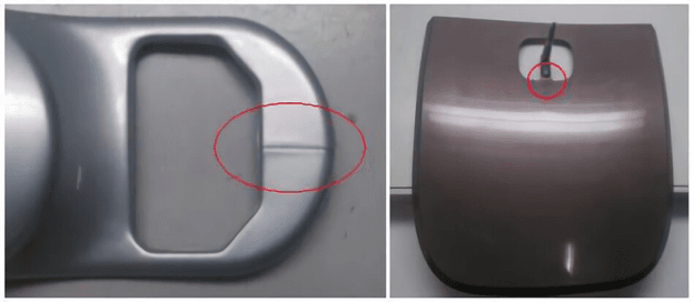
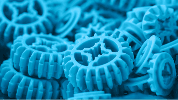
In injection molding, the weld line is the seam that forms between the two halves of the mold. The resulting string in the section is excellent and challenging to detect.
Injection molding processes require the highest quality control and technical expertise due to the numerous potential sources of aesthetic and functional defects in the finished plastic part. Consumers will typically not accept products with these defects, significantly increasing production costs. Pieces with too obvious flaws to ignore or prevent the part from performing its technical function are typically scrapped.
This line typically does not alter the product’s overall shape or dimensions. The degree to which it shows up depends on how shiny the mold is, what the material is, and what the processing settings are. Since injection molding requires a two-piece mold, the seam will always be visible in the final product, no matter how hard anyone tries to hide it.
Welding lines in injection molding are discussed along with their consequences and solutions in this guide.
Where Do Welds, Knits, and Melts Form, and What Causes Them?
Imperfections in the final product of plastic injection molding are referred to by various names, including weld lines, knit lines, and meld lines.
A weld line can also be known as a knit line. A line will form on the surface of the plastic at the point where two separate flows meet. These currents barely touch one another to keep from strongly welding, knitting, or merging, forming a new barrier.
A fusion line, more visible on the plastic surface, is formed at the intersection of two liquid flows. Instead of merging into one another, the two currents split off and merge in a different direction.
These flaws in a part’s molecular structure can reduce its durability. To examine and find the right solutions for each type, let’s look at the distinctions between weld and meld lines.
How do Weld Lines Appear?
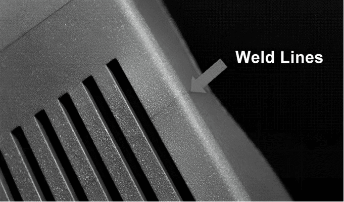
When two or more flow fronts fail to “knit” together during molding, a weld line (also called a knit line) forms at the point where the fronts meet. These cracks are most common near any hole or obstruction in the molded piece.
Weld lines are also referred to as meld lines among machinists. Both share a similar design, but there is one key distinction. The divergence is due to the oblique angle at which the two flow fronts meet. Weld lines never have a meeting angle greater than 135 degrees. A meld line is formed at an angle of encounter greater than this.
The formation of this phenomenon can be comprehended with an understanding of plastic flow. Plastic flows have a continuous, smooth front when they occur. If this flow doesn’t bump into anything, it will continue to be smooth the whole way through.
A pin, for example, can cause the flow to split in two, one branch going around the pin and the other continuing on its way. This means that the object now has two distinct sides, one of which runs through it and the other lies on the other side.
There is a brief trough where the currents reunite at the front. The weld line, known as the knit line, is a very thin depression. However, the weld line might break up somewhere along the flow. As a result, the two flow fronts may eventually merge to form a single frontal lobe. Plastic Injection Molding Weld Lines will remain until this process is completed.
Weld lines form as a result of the following steps:
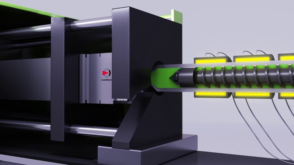
Flow Convergence: Injecting the molten plastic into the mold cavity causes the plastic to split and flow in multiple directions.
Flow Front Convergence: Eventually, the fronts of the two flows will meet again, usually on the far side of the obstruction.
Merging of Material: A weld line is formed when two flow fronts merge, solidifying into a single line. A region of weaker bonds than the rest of the component is produced due to the merging process.
Weld lines vary in appearance and placement based on several factors, including but not limited to mold design, insert placement, material properties, and processing conditions. Both external and internal weld lines compromise the strength of the component.
How Do Weld Lines Affect The Plastic Parts?
The quality of plastic goods may suffer noticeably at the weld line. For instance:
Structural Integrity: A product’s overall strength and stability can be compromised by weld lines. They cause an area of reduced bonding, which makes the part more likely to fail or break when subjected to strain.
Aesthetics: Visible weld lines on the product’s surface can detract from its overall aesthetic quality. They can take the form of lines, marks, or discoloration and lower an item’s perceived quality and value.
Functionality: Weld lines can sometimes hinder the product’s intended use. For instance, fluid-carrying parts may cause leaks or block the product’s intended flow path, reducing its effectiveness.
Durability: Because of the increased stress at the weld line, the product may fail sooner than expected due to wear, fatigue, or cracking. The item’s strength and longevity may suffer as a result.
Customer Perception: Customer perception of weld lines is typically negative. Customers may become dissatisfied if they are made aware of them.
Manufacturers take great care in mold design, material selection, process optimization, and quality control measures to reduce the occurrence and impact of weld lines. By addressing weld line issues, manufacturers can increase product strength, aesthetics, functionality, and customer satisfaction.
Weld line: What causes it, and how to fix it
Low temperature
Low-temperature melt is easy to weld but has poor splitting and converging performance. When the temperature of a plastic part is too low, welding can occur between the inner and outer surfaces. Increasing the barrel’s temperature or the nozzle or lengthening the injection cycle will accomplish this. The temperature of the mold must be increased while controlling the cooling water flow.
Welding plastic components typically results in a weak joint. By increasing the local temperature of the welded area of the molded part, we can increase the strength of the weld. This is accomplished by locally heating the corresponding part of the weld in the mold.
In low-temperature molding, the injection speed and pressure can be modified to enhance the melt confluence if necessary. A small amount of lubricant can also improve melt flow properties if added to the raw material formulation at the right time.
Damage from mold
Welding failure is typically caused by molten material splitting and converging. Hence, the structural parameters of the mold casting system have a significant impact on the welding condition of the flow material. Using the gate form with the least amount of shunt and positioning the gate wisely can prevent inconsistencies in filling rates and interruptions in filling flow. One-way gates are preferred whenever possible.
The melt does not mix from opposite directions when using a gate, so no weld marks are produced. The main channel inlet and the sub-runner cross sections are too small, and the number of gates in the casting system of the mold is incorrect.
High material flow resistance leads to subpar weld quality and a relatively visible weld line on the plastic’s surface. It’s important to pinpoint the auxiliary flow route, reduce the number of gates, and enlarge the runner and sub-runner diameters. A cold hole must be drilled into the mold before injecting the high-temperature melt into the cavity and forming the weld line.
Weld marks from the plastic component are transferred to the flash via a shallow groove made in the mold at the point of generation. This is due to the fact that the weld line does not shrink after the flash has been created. The winglet is usually removed after molding to prevent a weak line of weld.
Insufficient ventilation for mold
When the melt’s weld line meets the mold line or caulking, the cavity’s trapped air is released. However, if the vent hole is not in the right place, the air that remains in the cavity after the flow has passed is unable to escape, the bubble is subjected to excessive pressure, and the bubble’s volume gradually decreases because the weld line does not align with the mold line or the caulking.
We’ve whittled it down to a single core issue at last. Because the molecules’ kinetic energy is converted to thermal energy at high pressure, the air’s melting point rises. A yellow spot will form at the fusion point when the temperature is just above the decomposition temperature of the raw material. If the fusion joint is heated to a temperature higher than the raw material’s decomposition temperature, a black spot will form.
This sort of spot can be found on the exterior of plastic components near a weld line. During operation, these spots should not be confused with impurity spots. These flaws typically result from insufficient mold exhaust, the carbonization point formed after molten material is pyrolyzed.
See if the mold’s vent hole and gate are free of solidified material or other melt objects after such a failure. After the obstruction has been removed, the carbonization point may still be present, in which case a vent hole will need to be drilled in the feed point of the mold.
We can increase the rate of convergence by relocating the gate, modifying the clamping force, and enlarging the exhaust gap. When it comes to the nuts and bolts of the process, you can play it safe by, say, lowering the injection pressure, the injection time, or the material and mold temperatures.
Improper use of release agent
When welding plastic, using too much or the wrong kind of release agent can leave visible marks on the surface. Injection molding rarely requires even trace amounts of release agents and then only for particularly challenging features like threads. In most cases, a smaller amount of release agent is preferable.
Release agents must be chosen with consideration for molding conditions, plastic part geometry, and a wide range of materials. To give you an example, pure zinc stearate isn’t compatible with polyamides or clear plastics, but it is when combined with oils.
Another example is the silicone oil toluene solution, which has many uses and a long shelf life after brush application but is difficult to use because it needs to be heated and dried.
<3>Unreasonable structural design of plastic parts<3>
The quality of the weld can suffer if the plastic component’s wall thickness is insufficient in relation to the amount of insert used. Due to the rapid solidification of the melt, the ease with which defects can be created, and the fact that melts always meet at thin walls during the filling process, weld lines are inevitable when forming components with such small cross-sections.
When plastic components are welded, their performance drops because of the thin weld lines. For plastic components, the thinnest section of the part’s structure should be made thicker than the minimum wall thickness permitted during molding. Wall thickness should be kept constant, and inserts should be used sparingly.
Techniques for Fixing Weld Lines
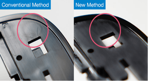
Whether it’s for reasons of aesthetics or strength, weld lines can be minimized or relocated in a number of ways. Fixing a weld line issue, however, may lead to yet other, more serious complications. Before making any of the following or any other changes to address weld lines, you should always consult your plastic injection molding contract manufacturer.
- Increasing the mold or plastic material’s temperature can facilitate a more complete fusion of the two flow fronts.
- To inject hot plastic into the mold cavity, a gate must be installed. The weld lines on a component are directed by the position of these gates. Before a mold is cast, the gates can be rearranged so that the weld lines are not in plain sight.
- Mold filling time is affected by wall thickness. If the fill time is shortened or lengthened, the flow fronts will converge at a new point, shifting the weld line’s position.
- Changing the design of the component could reduce the number of flow fronts from multiple to single.
- By decreasing the size of the runner system, the manufacturer can raise the temperature of the molten plastic at the beginning of each flow, preventing the formation of weld lines.
- The injection rate can be increased to hasten the filling of the mold and prevent the material from cooling too quickly, thereby reducing the likelihood of weld lines. In addition, changing the velocity can shift where the flow fronts meet, thereby relocating the weld line.
- By switching to a raw material with a lower viscosity or melting point, we can potentially enhance flow properties and reduce or relocate weld lines.
Injection-molded components can be machined with features like holes after molding is complete to avoid the need for welds.
There are several types of defects that can have a significant effect on production speeds, not just weld lines. This is why it’s so important to take precautions before things get out of hand during product development. Taking precautions at various points in production can greatly reduce the number of injection moulding defects.
Get in contact with longsheng to find out how our staff can help you out with your project and cut down on production errors.