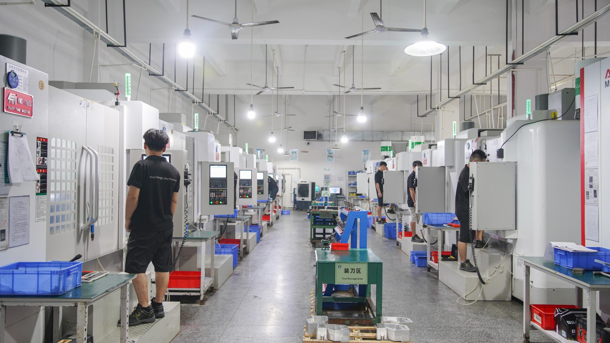
Face milling machines are a fundamental and indispensable tool in the grand symphony of modern manufacturing, one of the principal tools for machining large, flat or continuously curved workpieces cost-effectively. They are purpose-built for one operation: using high-speed, multi-edged face milling cutters with high cutting forces to mill large areas of workpiece surfaces at high speed and with high precision, perpendicular to the spindle. Their main virtue is in successfully removing excess material, finally presenting a smooth, flat surface with precise dimensions and desired geometry.
Compared to other forms of milling machines, face milling machines are renowned for their high rigidity, heavy table load capacity, and high spindle power. These qualities make them a pure workhorse for machining large, closely milled parts, i.e., heavy machine tool bases, large housings, large flat panels, and precise mold parting surfaces. Be it machining chassis components for the automotive industry, structural parts for the aerospace industry, energy equipment bases, or important surfaces of general machinery, face milling machines, through their high-efficiency, stable, and reliable machining ability, have grown to be an indispensable cornerstone of large-scale, high-quality surface machining in modern industry.
Quick Reference Table Of Basic Knowledge Of Face Milling Machine
| Features | Brief Description |
|---|---|
| Core Function | Mainly performs large-area flat surfaces or simple contour milling perpendicular to the spindle direction. |
| Key Components | Rigid bed/column, high-power spindle (usually vertical), large movable table, face milling cutter. |
| Processing Objects | Large casting and forging blank surfaces, workpiece surfaces requiring high flatness, parallelism, or surface finish. |
| Key Advantages | High machining efficiency (large-diameter multi-edge cutter), excellent rigidity, high stability, and suitability for heavy cutting and large workpieces. |
| Typical Applications | Machine tool beds, engine blocks/cylinder heads, mold bases, structural flat surfaces, and finishing of flat parts. |
| Differentiation | The spindle is typically fixed vertically, focusing on flat surface milling (compared to the flexibility of universal milling machines). |
| Construction Type | Gantry structure, providing high rigidity and vibration resistance, suitable for carrying large workpieces. |
| Control Method | Typically CNC (Computer Numerical Control) or manual control, it supports high-precision programming and automated operation. |
| Accuracy Index | High positioning accuracy (usually within ±0.01mm) and repeat positioning accuracy ensure the quality of the processed surface. |
Why Trust This Guide?Real-World Experience from LS Experts
The value of this guide lies not only in the definition but also in the wealth of experience that LS engineers have developed in solving real machining problems. We know:
- The challenge of a compromise between accuracy and efficiency: In large flat surface machining, how to achieve micron-level flatness and fine surface finish at high speed and high stock removal? It includes basic issues such as machine tool design, thermal deformation control, and vibration suppression.
- The Significance of Reliability: When machining the key components (such as machine tool bases and large molds), equipment downtime or precision instability will result in tremendous losses. We understand the significance of stable and reliable operation.
- Confronting the Challenge of Complex Workpieces: Large workpieces generally possess complicated shapes, are difficult to clamp, and require high material removal. Process optimization and tool and parameter selection are extremely significant in practical application.
- Long-Term Cost Considerations: Purchase price is only the beginning; total value of maintenance costs, energy consumption, service life, and machining productivity are vital.
We believe that LS Precision Manufacturing’s technical capability, manufacturing experience, and customer commitment are the underlying reasons this guide is accurate and the best reason for you to choose LS as your partner. If you have any special machining needs or challenges, we are always here to leverage our experience to provide solutions to you.
What Is A Face Milling Machine?
A face milling machine is a machine tool that is specially designed for efficient and high-precision milling of large, flat workpiece surfaces (planes). It is not a general-purpose, multi-purpose milling machine but a special-purpose machine that is well optimized for plane machining. Its ultimate objective is to remove excess amounts of material from large workpieces quickly and to achieve better flatness and parallelism. Compared to conventional vertical or horizontal milling machines, face milling machines achieve specialized advancements in the following three aspects:
Large Worktable and Strong Rigidity
A large worktable (usually greater than 1-2 meters) and a heavy bed structure can withstand large workpieces and cutting vibration. Conventional milling machines have weak column or cantilever structures, while face milling machines usually use box-type columns or gantry frames to ensure stability for heavy cutting.
High-Power Spindle and Specialized Cutterhead
Featuring a high-torque spindle (often over 15kW) and a multi-edge face milling cutterhead (diameters reaching 300mm), face milling machines achieve far higher single-pass cutting depths and feed rates than conventional milling machines, making them eligible for high-speed stock removal. Vertical milling machines are largely used in small area or complex contour machining, with both limited power and tool coverage.
Clear Process Positioning
Within the manufacturing process, face milling machines primarily deal with roughing and semi-finishing procedures, quickly establishing reference surfaces and setting the stage for subsequent finishing procedures (e.g., grinding). Universal milling machines, on the other hand, are of a more universal nature, drilling, grooving, and other operations being feasible, albeit without the efficiency and precision of face milling machines.
Face milling machines, in a “dedicated machine for a specific purpose” philosophy, through reinforced structures and high-removal design, have become significant machinery for high-volume surface machining. They are particularly apt for the initial machining of large workpieces such as machine tool bases and steel plates.
How Does A Face Milling Machine Work?
In machining, particularly in dealing with large workpieces or high-precision flat surfaces, face milling machines are essential. They are a special type of milling machine that is intended for the efficient machining of large flat surfaces. So, how does this apparently big machine actually operate? LS Precision Manufacturing will give a step-by-step explanation of the working principles and machining process of a face milling machine.
Core Mission: Efficiently Remove Material and Produce a Flat Surface
The basic task of a face milling machine is straightforward: it uses a rotating multi-edge tool (a face milling cutter) to remove excess material from the workpiece surface, resulting in a smooth, flat surface with wanted dimensional accuracy. It is well suited to machining large flat surfaces, far more efficiently than face milling line-by-line with end mills.
Working Principles and Steps of a Face Milling Machine
The working process of a face milling machine can be summarized as follows:
1. Clamping of Workpiece: The workpiece to be machined is securely clamped onto the worktable, generally with the assistance of tools such as clamps, clamps, vises, or T-slot bolts. Solid workpiece fixturing is necessary for machining accuracy and safety.
2. Tool Mounting: Select a face milling cutter with the appropriate diameter and number of teeth, mount it on the spindle shank, and tighten it.
3. Parameter Setting:
- Spindle Speed: Set the proper rotational speed (RPM) based on the tool material, diameter, workpiece material, and planned cutting conditions (roughing/finishing). This sets the linear speed of the cutting edge when it touches the workpiece.
- Feed Rate: Defines how quickly the workpiece (or tool) moves in the feed direction (typically mm/min or inch/min). This determines how much material each tooth removes and the rate of material removal.
- Depth of Cut: By traveling the spindle head along its Z-axis, you can set the vertical depth (ap) of engagement the tool will penetrate the workpiece in a single pass. This depth is deeper for roughing and shallower for finishing.
- Width of Cut: It is the width (ae) of the workpiece surface that is covered by the tool in a single pass. Face milling cutters are generally larger in diameter than the width of the workpiece and can cover the entire surface in a single pass.
4. Start the operation:
The spindle motor is activated, causing the face milling cutter to revolve at high speed (main motion). Here, the cutting force is generated.
The feed mechanism is activated, causing the worktable (and workpiece) to advance in a constant direction of feed (usually crosswise to the spindle axis) (feed motion). Sometimes the spindle head moves in addition to the cutter.
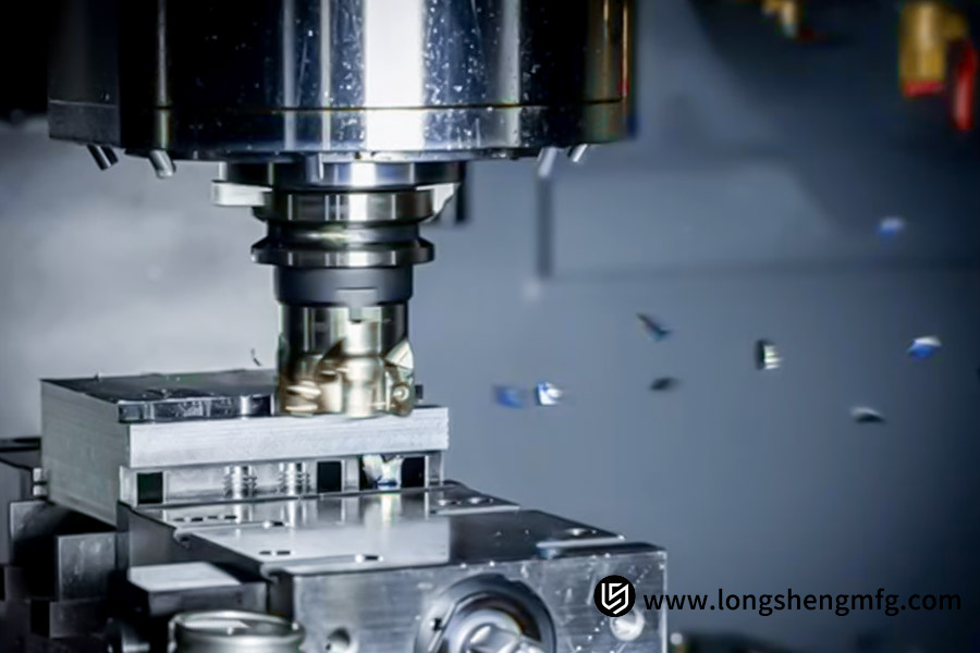
5. Cutting Process (Basic Principle):
- On the high-speed rotating face milling cutter, a number of carbide inserts simultaneously enter the workpiece surface in succession.
- Each insert acts as a tiny chisel, removing a thin layer of metal material (chips) from the workpiece through the action of rotation and workpiece feed combined.
- The large number of inserts (multi-edge cutting) and the large tool diameter (covering a large area) make the material removal rate very high, and it is possible to generate large surface areas in a short time.
- Chips formed by cutting are either thrown away by the rotating tool at high speed or washed away by coolant.
- Coolant is sprayed continuously into the cutting zone, cooling the workpiece and tool, lubricating and reducing friction, and carrying away the chips.
6. Finishing: As the worktable moves the workpiece in such a way that the entire surface to be machined passes beneath the rotating milling cutter, a single pass is completed, producing a flat surface.
7. Repeat and Finishing: For operations where a greater depth of cut or improved surface finish is required:
- Roughing: Use a deeper depth of cut and quicker feed rate to remove the majority of the stock quickly.
- Finishing: Use a smaller depth of cut, a lower feed rate, and a sharper insert (or switch to the finishing insert), perhaps with an increase in speed to achieve a better surface finish and improved dimensional accuracy. More than one finishing cut may be required.
8. Stop and Measure: After machining, stop the spindle and feed. Remove the workpiece and use precision measuring tools (such as a straightedge, dial indicator, or height gauge) to check the flatness, parallelism, dimensional accuracy, and surface finish of the machined surface.
What Are The Main Structural Components Of A Face Milling Machine?
| Structural Components | Main Function | Key Features |
|---|---|---|
| Bed | Provides basic support and stability | Strong, rigid, and with excellent vibration damping |
| Table | Clamps and secures the workpiece | Precise movement in the X-axis (left and right) and Y-axis (forward and backward); sometimes also includes Z-axis (lift and lower) functionality |
| Column | Vertically supports the spindle head | Mounted at the rear of the bed, it provides rigid vertical guidance |
| Spindle head | Mounts and drives the spindle, carrying the vertical motion mechanism | Z-axis (vertical) movement along the column guideway controls cutting depth |
| Spindle | Rotates at high speed, mounts and drives the face milling cutter | Highly rigid and precise, driven by a motor (often internal) |
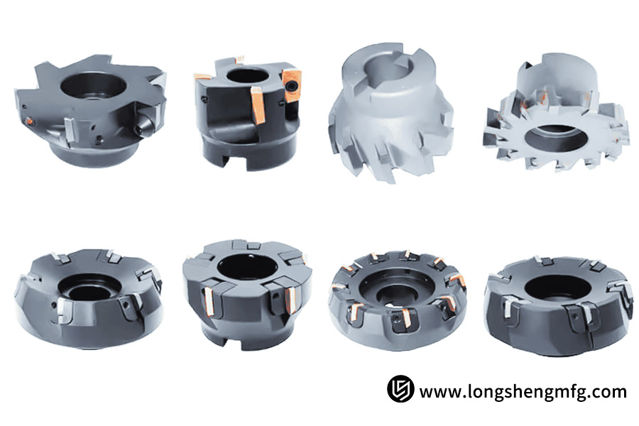
| Face milling cutter | Directly performs the cutting task | Disc-shaped, with multiple carbide inserts (or integral teeth), for circumferential/face cutting |
| Feed System | Drives the worktable (workpiece) and/or spindle head (tool) in relative motion | Provides precise, controllable feed motion in the X, Y, and Z axes (manual or automatic) |
| Coolant System | Provides cutting fluid | Cooling the tool/workpiece, lubrication, flushing away chips, and extending tool life |
The face milling machine completes large-surface, high-precision, and high-efficiency milling processes with a rigid supporting structure (bed, column), a high-precision relative motion system (worktable, spindle head, feed system), an efficient cutting mechanism (spindle, face milling cutter), and an assistant system (coolant).
What Are The Main Application Areas Of Face Milling Machines?
As important equipment in the metal processing industry, face milling machines assume a central role in numerous industrial fields with their efficient and precise surface machining operations.
1. Heavy Machine Production
Face milling machines perform essential machining operations in heavy machine production:
- Machine Tool Part Machining: Precise flat reference surface milling for major castings such as machine tool beds, bases, and columns.
- Guideway Surface Treatment: Machining of mounting contact surfaces of various linear and sliding guides.
- Equipment Mounting Surfaces: Providing high-precision assembly surfaces for large equipment.
Common machining accuracy can reach IT7, surface roughness of Ra1.6-3.2μm.
2. Mold Manufacturing Industry Applications
The mold manufacturing industry demands face milling machines to possess very stringent surface machining standards:
- Mold Processing: High-precision injection mold and die-casting mold milling. Template parting surface
- Mold base preparation: Face and locating surface machining of standard mold bases
- Big molds: Milling the base face of car panel molds
Face milling cutters are typically 200-400mm diameter, having good cutting efficiency.
3. Key processes in energy equipment manufacturing
In the energy equipment sector, face milling machines solve the machining of huge components’ problems:
- Wind turbine components: End face machining of gigantic castings such as hubs and bases
- Power generation equipment: Turbine casing and generator base assembly surfaces
- Nuclear power equipment: Pressure vessel support surface milling to precision
A high-power spindle (30-50kW) is required. High-intensity cutting
4. Machining of construction machine core components
Construction machine reliability begins with precise surface machining:
- Chassis components: Milling of the mounting surfaces on excavator/loader chassis
- Structural components: Reference surface preparation of booms, dipper arms, and other components prior to welding
- Slewing bearings: Precise machining of contact mounting surfaces
Heavy-duty face milling machines are used mainly, and worktables support a loading capacity of 10-20 tons
5. Automotive production lines of manufacturing critical processes
Mass production in the automotive industry relies on face milling technology:
- Powertrain: Machining of mating surfaces of engine blocks and cylinder heads
- Transmission system: Precision milling of many mounting surfaces on transmission housings
- Chassis components: Datum surfaces of suspension components and axles machining
CNC face mill machining centers are often used to enable μm-level control of precision
6. Aerospace Precision Machining
The aerospace industry has extremely stringent requirements for surface machining:
- Structural components: Machining datum surfaces of fuselage frames and aircraft wing spars
- Landing gear: Accurate milling of mounting contact surfaces of load-carrying components
- Spacecraft: Rocket part and satellite bracket surface machining
Thanks to high-rigidity face milling machines that employ dynamically balanced tool systems
From aircraft precision parts to heavy equipment, face milling machines, through their superior surface machined characteristics, have become an indispensable key element in modern manufacturing. As technology for CNC grows stronger, modern face milling machines are leaning towards more precision and efficiency, constantly contributing to the betterment of manufacturing in all industries. In selecting a face milling machine, companies should consider essential parameters such as table size, spindle power, and accuracy level based on their specific requirement in machining for optimal performance.
Case Study: Repairing The Mounting Surface Of A High-Precise Machine Tool Guide Rail
1. Client Background
Large machine tool producer. The mounting surface of a heavy-duty linear guideway, as a principal element of their high-precision CNC machine tools, had experienced infinitesimal localized deformation and wear as a result of prolonged utilization and stress relief. Consequently, the guide rail mounted was no longer as even and precise in movement as originally.
2. Client Pain Points:
- Large Flatness Requirements: The guide rail length was more than 2 meters, and hence total flatness of ≤ 0.02mm/m and overall flatness of ≤ 0.05mm over the whole length were necessary.
- Large Surface Quality Requirements: Surface roughness Ra ≤ 0.8μm was required to ensure guide rail mounting stability and contact stiffness.
- Hard Material: The guide rail was made from high-strength alloy cast iron (HT300), which is extremely hard and resistant to wear, being difficult to tool and machine.
- Strict Schedule: The machine tool was out of commission for maintenance, and the customer needed a speedy return to production.
- Repair rather than replace: Replacing the whole base is costly and time-consuming, and thus localized, precision repairs were favored by the customer.
3. LS Solution
High-accuracy electronic level and laser interferometer are utilized to precisely measure the deformed zone.
- Optimized Process: Computer-controlled sequential milling is employed: roughing milling quickly removes over-stock, and then semi-finishing and finishing milling (with a very low depth of cut and multi-tooth finish milling cutter) slowly achieves precision and surface finish requirements. Optimized cutting parameters are utilized to minimize micro-chipping.
- Key Equipment: A heavy, high-rigidity CNC gantry milling machine (with precision guideways/lead screws and a high-precision spindle) is employed to provide machining stability and accuracy.
- Reliable Fixtures: Designed special tooling rigidly holds the workpiece, reduces deformation, and provides accurate alignment.
- Process Monitoring: Online monitoring of cutting status and in-process measurement after key steps are taken.
4. Results and Value:
- Exceptional Accuracy: Base surface flatness is 0.015 mm/m (0.04 mm cumulative) well in excess of specification.
- Exceptional Surface: Stable roughness at Ra 0.6-0.7μm.
- Successful Delivery: Exceptional quality within a very strict timescale.
- Significant Cost Saving: Over 60% reduced cost and weeks saved in time compared to a replacement base, which enables the customer to be quickly up and running again.
5. Customer Feedback:
“LS’s engineering team demonstrated phenomenal professionalism and technical expertise. To our short-delivery, high-precision needs, they designed a precise, effective face milling restore solution, which gave an ideal finish. They went beyond our immediate requirements, with the restored surface quality exceeding the original! This is a tribute to LS’s remarkable expertise in large-scale precision surface machining and makes them a great partner.”
FAQs
1. What is the purpose of face milling machines?
Face milling machines are applied to high-speed, high-accuracy machining of large flat surfaces on large workpieces. Some examples of typical uses include machine bases, mold parting surfaces, housing mating surfaces, flat panels, and structural part datum surfaces. They are founded on their underlying design using large-diameter cutters and a powerful spindle for rapid material removal from large surfaces, and thereby are very well suited to cutting heavy workpieces with high flatness and surface integrity.
2. What is the primary difference between a face milling machine and a regular milling machine (vertical/horizontal)?
It is primarily their flat machining optimization: face milling machines possess an extensive worktable load-bearing surface, high structural stiffness much more than in regular milling machines (cutting deformation resistance), greater spindle motor power (with heavy cutting support), and maximized clamping for large workpieces. This makes them much better than conventional vertical or horizontal milling machines when it comes to stability, efficiency, and precision in efficiently machining large flat areas such as valve flanges and machine tool beds.
3. How accurate in machining can a face milling machine be?
High-precision face milling machines are good for truly superb precision: flatness typically falls as low as 0.02mm/m (and some of the best models obtain even lower, below 0.01mm/m), and surface roughness as low as Ra 0.8μm or even lower (in finish milling). Actual precision depends on a number of factors, including the geometric accuracy grade of the machine tool, spindle dynamic stiffness, guideway condition, condition of the tool system, and optimal selection of cutting parameters (e.g., feed rate and depth of cut) and cooling technology.
4. What should I consider when selecting a face milling cutter (face milling cutter head)?
Selection must be carefully considered: ① Work material (steel, cast iron, aluminum alloy, etc., which determines the selection of insert material: carbide, CBN, or PCD); ② Processing stage (for roughing, select a cutter head with low teeth and high chip pocket; for finishing, select a cutter head with high pitch density to improve surface quality); ③ Machine tool capability (cutter head diameter should be within machine power and interface capacity to avoid overloading); and ④ Geometric angles (e.g., rake angle and lead angle, which influence cutting forces and surface texture). Carefully balancing these parameters is key to ensuring efficiency and quality.

Conclusion
Face milling machines are indispensable “surface machining experts” in modern manufacturing. With their exceptional rigidity, powerful cutting capabilities, and high productivity, they occupy a central position in the surface machining of large workpieces. Whether in mold manufacturing, which demands extreme precision, or in heavy machining requiring efficient stock removal, a reliable, high-performance face milling machine is a key cornerstone for ensuring product quality and improving production efficiency.
If you’re looking for a solution that consistently produces high-quality surfaces, easily handles heavy cutting loads, and maximizes productivity, LS face milling machines are your trusted partner. With our deep expertise and focus on quality, we offer solid rigidity, precision manufacturing, and exceptional reliability to help you overcome your machining challenges and achieve significant productivity gains. Contact an LS sales engineer today to equip your shop with a true surface machining powerhouse and embark on a new chapter in efficient finishing!
 📞 Phone: +86 185 6675 9667
📧 Email:info@longshengmfg.com
🌐Website:https://www.longshengmfg.com/
Disclaimer
The content appearing on this webpage is for informational purposes only. LS makes no representation or warranty of any kind, be it expressed or implied, as to the accuracy, completeness, or validity of the information. Any performance parameters, geometric tolerances, specific design features, quality and types of materials, or processes should not be inferred to represent what will be delivered by third-party suppliers or manufacturers through LS’s network. Buyers seeking quotes for parts are responsible for defining the specific requirements for those parts. Please contact to our for more information.
Team LS
This article was written by various LS contributors. LS is a leading resource on manufacturing with CNC machining, sheet metal fabrication, 3D printing, injection molding,metal stamping and more.


Valuable information. Lucky me I found your website by accident, and I am shocked why this accident did not happened earlier! I bookmarked it.