

CNC milling technology is a very important technology in the field of modern manufacturing, which brings many advantages to manufacturers. From raw material to final product processing, the application of CNC milling technology makes production more accurate, efficient and sustainable.
In this article, we will explore the intricacies of operating CNC milling machines and discuss the essential machining conditions that ensure optimal results. Whether you are an aspiring CNC machinist or simply curious about this advanced manufacturing process, read on to acquire a deeper.
What CNC milling technology?
CNC milling technology is a precision machining process based on computer numerical control systems. In CNC milling, the production of complex shapes can be achieved by cutting and processing the workpiece in different directions.
The first step in operating a CNC milling machine is to correctly select and install the cutting tools. Different types of workpieces require the use of different types of cutting tools, depending on their shape, material, and processing requirements. Once a suitable tool is selected, the operator needs to install it correctly on the tool holder of the CNC milling machine and ensure that the tool is tightly fixed to avoid loosening and swinging.
Setting of CNC milling machining conditions
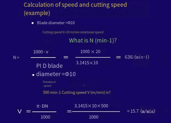
In CNC machining, after selecting a cutting tool, many people usually do not understand how much cutting speed and speed to choose, but only through experiments, as long as there are no special problems, they think it is possible. Doing so is very dangerous, and the common problem is cutting, or causing material to melt or burn. Is there a scientific calculation method? The answer is yes.
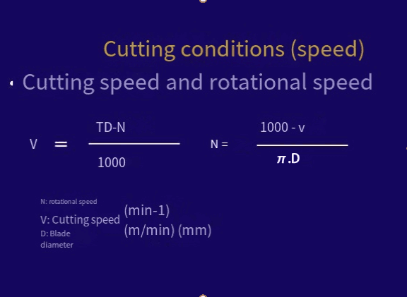
1.Milling cutting speed
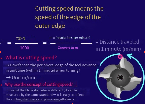
Milling cutting speed refers to the instantaneous speed of the selected point on the tool relative to the corresponding point of the workpiece.
Vc = PI DN / 1000
Vc Cutting speed, unit m/min
N Tool speed (unit: r/min)
D milling cutter diameter, unit mm
Cutting speed is affected by factors such as tool material, workpiece material, machine component rigidity and cutting fluid. Usually a lower cutting speed is often used to process hard or ductile metals, which belongs to strong cutting, in order to reduce tool wear and extend the service life of the tool.
Higher cutting speeds are often used to process soft materials in order to obtain better surface finish quality. Higher cutting speeds can also be used when small diameter tools are selected for micro cutting on brittle material workpieces or precision parts. For example, with high-speed steel milling speed, aluminum is 91~244m/min, bronze is 20~40m/min.
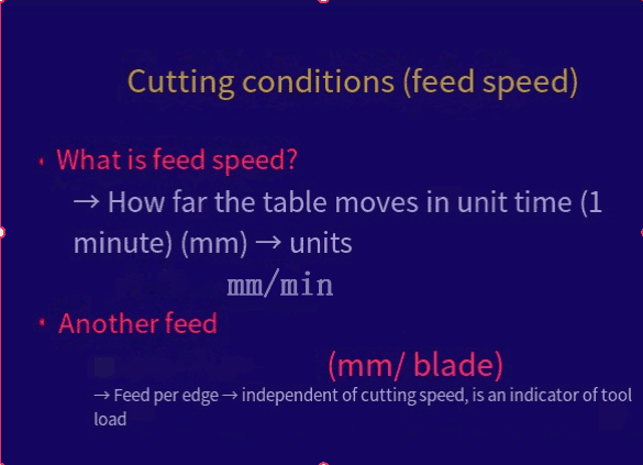
2.Feed rate
Feed speed is another equally important factor in determining the safe and efficient machining of machine tools. It refers to the relative cutting speed between the workpiece material and the tool. For multi-tooth milling cutters, since each tooth participates in the cutting work, the thickness of the workpiece to be machined depends on the feed speed. Cutting thickness will affect the service life of the milling cutter, and excessive feed speed will cause cutting edge damage or tool break.
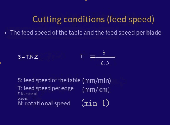
Vf = Fz * Z * N
Vf Feed rate, unit: mm/min
Fz Feed per tooth, unit mm/r
Z Number of tool teeth
N Tool speed (unit: r/min)
From the above formula, we only need to know the feed per tooth (cutting amount), the spindle speed, you can know the feed speed. In other words, knowing the feed amount and feed speed per tooth, you can find the spindle speed.
For example, the feed rate of high-speed steel milling cutter, when the tool diameter is 6 mm, the feed rate per tooth:
Aluminum 0.051; Bronze 0.051; Cast iron 0.025; Stainless steel 0.025

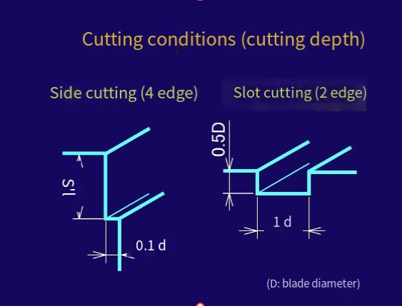
3.Depth of cutting
The third factor to consider when machining is the depth of cutting. It is limited by the amount of workpiece material cutting, the spindle power of the machine tool, the tool and the rigidity of the machine tool. Generally, the cutting depth of the steel end mill should not exceed half of the tool diameter.
For soft metals, the cutting depth can be greater. The end mill must be sharp and must be concentric with the end mill chuck when working, and the amount of overhang during tool installation must be reduced as much as possible.
4.Milling cutter condition table
V-coated XPM short-edge V-XPM-EDS-V-XPM-EMS
Groove machining
| Processing workpiece | Carbon steel and cast iron S50C.FC250 Loss rate 490-735Nml | Alloy steel SCM · SNCM · SNC Loss rate 735~980Nm |
| Data (mm) | Speed (min-1) | Feed rate (mm/min) | Speed (min-1) | Feed rate (mm/min) |
| 1 | 12500 | 63 | 11200 | 56 |
| 2 | 8300 | 75 | 5600 | 56 |
| 3 | 4500 | 95 | 3750 | 63 |
| 4 | 3550 | 106 | 2650 | 63 |
Common CNC milling techniques
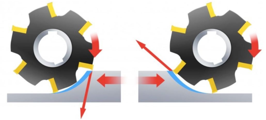
In CNC machining, the rotation direction of the milling cutter is generally constant, but the feed direction is variable. There are two common phenomena in milling processing: forward milling and backward milling.
The cutting edge of the milling cutter is subjected to impact loads every time it cuts in. In order to achieve successful milling, it is necessary to consider the correct contact between the cutting edge and the material during the cutting process and during the cutting process.
In the milling process, the workpiece is fed in the same or opposite direction to the direction of rotation of the milling cutter, which affects the cutting in and out of the milling process, as well as whether to use forward or backward milling methods.
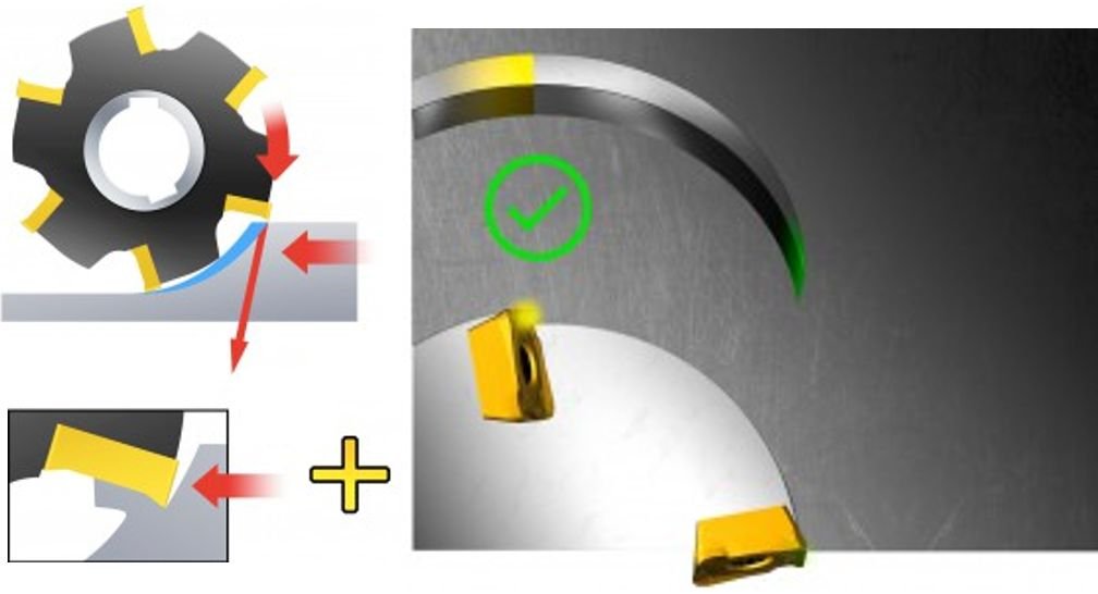
Golden Rule of Milling – From Thick to Thin
When milling, it is important to consider the formation of chips. The decisive factor for chip formation is the position of the milling cutter, and it is important to strive to form thick chips when the blade cuts in and thin chips when the blade cuts out to ensure a stable milling process. Remember the golden rule of milling, “from thick to thin,” to ensure that the thickness of the chips when the cutting edge is cut is as small as possible.
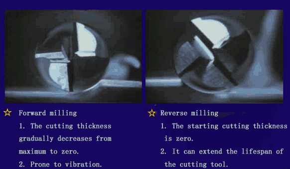
Forward milling
In forward milling, the cutting tool is fed in the direction of rotation. As long as the machine, fixture and workpiece allow, downmilling is always the preferred method.
In edge forward milling, the chip thickness will gradually decrease from the beginning of the cutting and eventually reach zero at the end of the cutting. This prevents the cutting edge from scraping and rubbing the surface of the part before it participates in cutting.
Large chip thickness is advantageous, and the cutting force tends to pull the workpiece into the milling cutter, keeping the cutting edge cut. However, because the milling cutter is easy to pull into the workpiece, the machine needs to handle the table feed clearance by eliminating the recoil.
If the cutter is pulled into the workpiece, the feed will increase unexpectedly, which can lead to excessive chip thickness and cutting edge breakage. In these cases, the use of forward milling is considered.
Reverse milling
In reverse milling, the feed direction of the cutting tool is opposite to its rotation direction.
The chip thickness gradually increases from zero until the end of cutting. The cutting edge must be forcefully cut in, resulting in scratches or polishing effects due to friction, high temperatures, and frequent contact with the work-hardened surface caused by the previous cutting edge. All of this will shorten the tool life.
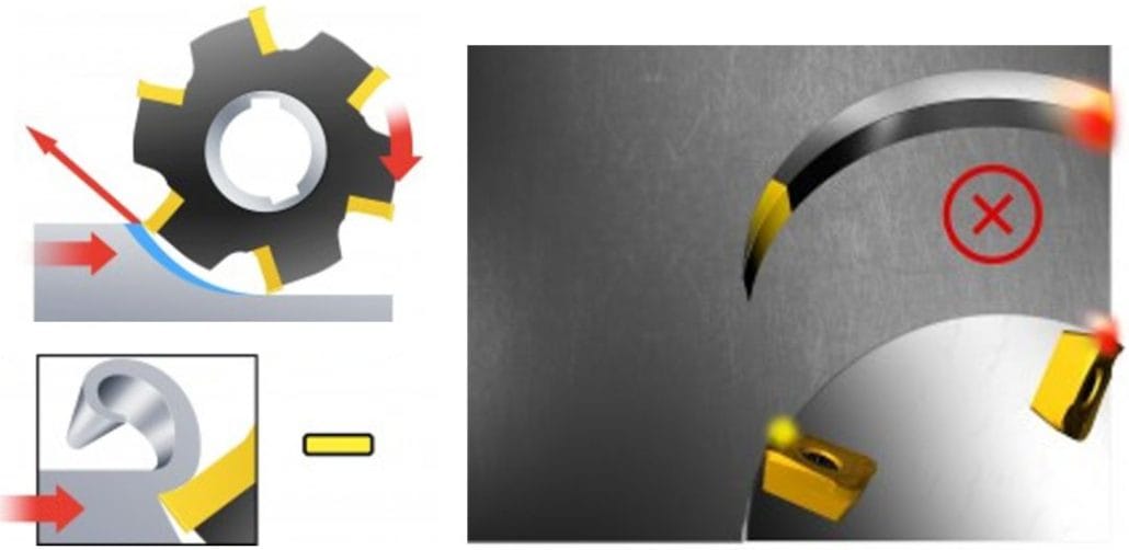
The thick chips and higher temperatures generated when the blade is cut out will lead to high tensile stress, which will shorten the tool life, and the cutting edge will often be damaged quickly as a result. It can also cause chips to stick to or weld to the cutting edge, which then carries them to the starting position of the next cut, or cause the cutting edge to break instantaneously.
The cutting force tends to push the cutter and the workpiece away from each other, and the radial force tends to lift the workpiece off the workbench.
When there is a large change in the machining allowance, the inverse milling may be more advantageous. When machining superalloys with ceramic blades, it is also recommended to use inverse milling, because ceramics are more sensitive to the impact generated when cutting into the workpiece.
Comparison Table of Forward milling and Reverse Milling
The feed direction of the cutting tool has different requirements for the workpiece fixture. Forward milling the reverse milling process, it should be able to resist lifting forces. During the milling process, it should be able to resist downward pressure. The following is a comparison table between these two milling methods:
| project | Forward milling | Reverse Milling |
|---|---|---|
| Cutting thickness | From large to small | From small to large |
| Gliding phenomenon | nothing | have |
| Tool wear | slow | fast |
| Cold hardness phenomenon on the surface of the workpiece | nothing | have |
| Effect on workpiece | Compression | lift |
| Eliminate the gap between the screw and nut | no | yes |
| vibration | large | small |
| Loss of energy | small | Up to 5% to 15% |
| Surface roughness | good | difference |
| Applicable occasions | finish machining | Rough machining |
conclusion
The development of CNC milling technology provides more choices and higher efficiency for manufacturing industries in various industries. Through reasonable operation and selection of appropriate machining conditions, CNC milling technology can help enterprises improve production efficiency, reduce costs, and provide higher quality products.
As a professional CNC milling service provider, we have advanced equipment and an experienced operation team, which can provide customers with high-quality CNC milling processing services. Whether it is small-scale production or customized processing, we can meet the needs of customers and provide comprehensive technical support.
If you need relevant CNC milling services, please feel free to contact us, and we will provide you with professional and efficient services
Mobile:+86 185 6675 9667(Gloria Wu)
E-Mail:gloria.wu@longshengmfg.com
FAQ
CNC milling is suitable for many different types of workpieces. It can process metal workpieces, such as aluminum, steel, copper, etc; It can also process non-metallic workpieces, such as plastic, wood, composite materials, etc. Different types of workpieces may require different cutting tools and processing parameters, so reasonable process analysis and tool selection are necessary before conducting CNC milling.
CNC milling is widely used in various fields, including aerospace, automotive manufacturing, electronic equipment, medical devices, etc. In these fields, CNC milling can be used to manufacture various complex shaped components and molds, meeting the processing needs of different industries.
CNC milling requires equipment such as milling machines, CNC systems, cutting tools, and workpiece fixing devices. At the same time, operators need to have technical knowledge in programming and operating CNC systems.