

The efficiency and quality of CNC machining largely depend on the reasonable selection of speed and feed. By deeply understanding these Committed step, you will be able to achieve better results in CNC machining and improve production efficiency.
In this article, we will explore the calculation methods of speed and feed in CNC machining to help you better understand and apply these key knowledge.
Concept of CNC machining speed and feed
In CNC machining, speed refers to the speed at which the spindle rotates, usually expressed in revolutions per minute (RPM). Feed refers to the speed at which the tool moves on the workpiece, usually expressed in millimeters per minute or millimeters per second. The speed and feed rate determine the cutting speed and cutting force, which in turn affect the cutting quality and efficiency.
CNC machining speed and feed calculation
The calculation of rotational speed and feed in CNC machining requires testing and optimization based on specific materials, tools, and working conditions. Each type of tool will adopt different machining parameters for different machining materials.
In the field of CNC machining, tool manufacturers usually optimize tool materials and develop more targeted coating technologies to improve machining efficiency.
By combining various elements in the material, we can see thousands of machinable raw materials. To process these materials, we must know the machining performance of this material and also know the methods that should be optimized for machining
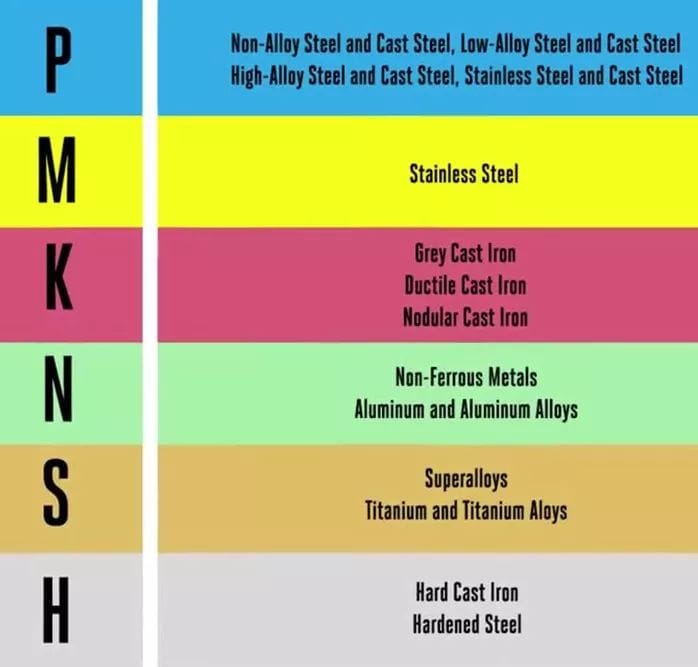
According to the ISO 531:1966 international standard, the materials that can be machining are divided into six categories, which are:
P represents the steel material;
M stands for stainless steel material;
Cast iron material represented by K;
Non-metallic materials represented by N;
S stands for high temperature material;
High hardness materials represented by H;
According to the tensile strength and hardness of the material, tool manufacturers classify the material in these categories. If we can not find the machining performance parameters of the material to be processed in these subclasses, the most feasible way is to consult the tool supplier, and believe that they are willing to help you solve this problem.
We will usually see the following formula in the tool manual

Before we talk about this formula, let’s recall that we learned the formula for the circumference of a circle:
C (circumference)=π (PI) *d (diameter)
According to this formula, we can conclude that for a tool with a diameter of D, the distance traveled by the outermost point of the tool is:
π *D
Then, when the tool is rotated at the frequency of n revolution / 1 minute, the distance traveled is:
n*π *D
According to the formula of time (T)× speed (V)= distance (S), the velocity Vc of the tool at any time point in this period of time is obtained:
Vc= (n*π *D) /1
The following formula is obtained through conversion:
n=Vc/(π *D)
VC is the cutting speed per minute (m/min), π is PI (about 3.14), and D is the tool diameter (mm).
Attention! Our tool uses millimeter (mm) as the unit, so the speed Vc in the previous formula is: millimeter/minute.
In order to get the best machining results, we need to choose the right cutting speed according to different materials and tool types. For materials with lower hardness, a higher cutting speed can be selected; For materials with higher hardness, the cutting speed should be reduced
After the conversion of length (1m=1000mm), we have this common formula:

After simplifying the equation, we have our final formula:

Attention!
Here the unit of D (tool diameter) is still mm (mm), and the unit of Vc (linear speed) becomes: M/min (m /min).
This formula also applies to turning, where the D represents the blank diameter.
We also found a video explaining the feed formula for you:
The basic formula for calculating CNC machining feed:
F is the feed speed (mm/min), n is the speed (RPM), Z is the number of tool edges, FZ is the feed per edge (mm/ edge).
The selection of feed speed should be adjusted according to different machining requirements. It should be noted that too high a feed speed may cause the tool to break or the quality of the machined surface to decline
There are two calculation methods for the spindle speed, the following examples: ① The spindle speed: one is G97 S1000, which means that the spindle rotates 1000 laps in one minute, which is usually called constant speed. The other is that G96 S80 is a constant linear speed, which is the spindle speed determined by the workpiece surface.
The feed speed is also available in two types G94 F100 means that the cutting distance is 100 mm in one minute. The other is G95 F0.1, which means that the tool feed size is 0.1 mm per revolution of the spindle
Speed setting
Use the speed formula to calculate the speed (unit is RPM) : speed = (cutting speed × 1000)/(π × tool diameter). The calculation formula of cutting speed is: cutting speed = linear speed of machining material × 1000. The calculation formula of linear speed is: linear speed = cutting speed of machining material × tool diameter × π.
According to the calculated speed range, select the appropriate speed according to the actual situation. Note that too high a speed will accelerate tool wear and machining heat accumulation, while too low a speed will affect machining efficiency and surface quality. It is recommended to properly adjust the speed range for actual machining tests to obtain the best speed setting.
Setting of feed rate
Use the feed rate formula to calculate the feed rate (unit: mm/min) : feed rate = cutting speed × cutting width × feed multiple. The calculation formula of cutting speed is: cutting speed = linear speed of machining material × 1000. The feed multiple here is determined according to machining requirements and tool selection.
According to the calculated feed rate range, select the appropriate feed rate combined with the actual situation. Too large feed rate may lead to too deep cutting, resulting in increased machining load; Too small feed rate may lead to low machining efficiency. It is also recommended to perform actual machining tests to obtain the best feed rate Settings.
CNC machining tool selection
Tool selection is carried out in the human-machine interaction state of CNC machining. The tool and handle should be correctly selected according to the machining capacity of the machine tool, the performance of the workpiece material, the machining procedure, the cutting amount and other relevant factors.
When selecting the tool, the size of the tool should be adapted to the surface size of the workpiece to be machined.
In production:
End milling cutter is often used to process the peripheral outline of plane parts.
When milling the surface, carbide blade milling cutter should be selected.
Choose high speed steel end mill when machining convex and groove.
Corn milling cutters with cemented carbide inserts can be selected when machining blank surfaces or roughing holes.
Ball end milling cutter, ring milling cutter, conical milling cutter and disc milling cutter are often used for the machining of vertical shape surface and variable bevel contour.
In the economic CNC machining, because the tool grinding, measurement and replacement are mostly manual manual, occupying a long auxiliary time, therefore, it is necessary to reasonably arrange the sequence of the tool. Generally, the following principles should be followed:
① Minimize the number of tools
②After a tool is installed, it should complete all the machining parts that it can carry out
③ Coarse finishing tools should be used separately, even if they are of the same size
④Milling before drilling
⑤ Surface finishing first, and two-dimensional contour finishing after
⑥ Where possible, the automatic tool change function of CNC machine tools should be used as much as possible to improve production efficiency.
Determination of cutting parameters in CNC machining
The principle of reasonable selection of cutting amount is that during rough machining, the main focus is on improving productivity, but economic efficiency and machining costs should also be considered; During semi precision machining and precision machining, consideration should be given to cutting efficiency, economy, and machining cost while ensuring machining quality.

(1) Cutting depth t
As long as the machine, workpiece and tool stiffness allow, t is equal to the machining allowance, which is an effective measure to improve productivity. In order to ensure the machining accuracy and surface roughness of the parts, a certain margin should generally be left for finishing. The finishing allowance of CNC machine tools can be slightly smaller than that of ordinary machine tools.
⑵ Cutting width L
Generally L is proportional to the tool diameter d and inversely proportional to the cutting depth. In economic CNC machining, the general value range of L is: L= (0.6 ~ 0.9) d.
(3) Cutting speed v
Increasing v is also a measure to improve productivity, but v is closely related to tool durability. With the increase of v, the tool durability decreases sharply, so the choice of v mainly depends on the tool durability.
In addition, the cutting speed also has a lot to do with the machining material, for example, when milling alloy just 30CrNi2MoVA with an end mill, v can be used about 8m/min; When milling aluminum alloy with the same end mill, v can choose more than 200m/min.
⑷ Spindle speed n(r/min)
The spindle speed is generally selected according to the cutting speed v. The calculation formula is:
Where d is the diameter of the tool or workpiece (mm).
The control panel of the CNC machine tool is generally equipped with the spindle speed adjustment (multiplier) switch, which can be adjusted in the whole multiple of the spindle speed during the machining .
(5) Feed speed vF
vF should be selected according to the machining accuracy and surface roughness requirements of the part, as well as the tool and workpiece material. An increase in vF can also improve production efficiency. When machining surface roughness requirements are low, vF can be selected to be larger.
During the machining process, vF can also be manually adjusted by the repair switch on the machine control panel, but the maximum feed speed is limited by the stiffness of the equipment and the performance of the feed system.
Examples and calculation methods
Below are two examples to help you better understand how to calculate the speed and feed of CNC machining.
Example 1: Steel machining
Suppose we need to process a piece of steel with a higher hardness. Based on experience, we can choose a speed of 1000 RPM and a feed speed of 200 mm/min. However, this is only an initial value and needs to be fine-tuned to suit the actual situation.
Example 2: Aluminum machining
For aluminum machining, due to its lower hardness, we can choose higher speed and feed. For example, we can choose a speed of 2000 RPM and a feed speed of 500 mm/min.
conclusion
When calculating the speed and feed of CNC machining, it is necessary to consider the characteristics of the material, the tool and the workpiece. Start with a rough value based on experience, and then fine-tune it according to the actual situation.
In CNC machining, in addition to speed and feed, you also need to pay attention to the following matters:
Use the right tools and fixtures
Check and maintain machine tools regularly
Special circumstances require additional security measures
By following these considerations, you can ensure the safety and efficiency of CNC machining.
FAQ
The choice of tool materials should be based on the type of material to be processed and machining requirements. Commonly used tool materials include cemented carbide, high-speed steel, ceramics and CBN. Carbide is suitable for machining hard materials such as stainless steel and high-strength alloy steel, while high-speed steel is suitable for machining soft materials such as low carbon steel and cast iron. Ceramics and CBN are commonly used to process superhard materials.
Tool life is affected by many factors. In addition to the right speed and feed, factors such as cutting depth, cutting speed, tool cooling and lubrication also affect tool life. In addition, the material and coating quality of the tool is also an important factor in determining the life