From a square piece of wood to a work of art, everything starts with understanding your lathe
You stand in front of a woodworking lathe full of potential, and the idea has taken shape in your mind. Your fingertips seem to be able to touch the round curves or delicate textures that are about to be born. Tools in hand, wood ready, the urge to create rushes in your blood. However, when your eyes fall on the lathe itself, a trace of hesitation quietly emerges-“What is the key component that can move smoothly back and forth, carry the tool, and determine the cutting path?”, “Also, what is the standard name of the core device that firmly clamps the wood and gives it rotational life?”
This ambiguity about the names of tool parts is not just a trivial terminology issue. It is an invisible barrier between inspiration and finished products. Failure to accurately refer to and understand every key part of the lathe is like trying to control a strange horse without knowing where the reins are. Without understanding the “language”, there is no real “dialogue”, let alone accurate “control”. This tiny cognitive gap is enough to stumble the smooth creative process and even cast a shadow on safe operation.
What are the various parts of a wood lathe called? This seemingly simple question is actually the key to opening the door to the art of turning. From the bed that supports everything, to the source of rotational power – the spindle and spindle box, to the tool holder that controls the tool and the flexibly positioned tailstock, each component plays an irreplaceable role. Knowing them, calling out their names, and understanding their collaboration is a solid first step in your precise transformation of rough wood into the artwork in your mind. Let’s start with naming, unlock the full potential of your lathe, and make every turning a confident creative journey.
Quick reference Table Of Core Components Of Wood Lathes
| Component name | Core function | Key subcomponents | Core role |
|---|---|---|---|
| Headstock | Drives the workpiece to rotate | Spindle, drive system (pulley/gear), chuck/panel | Provide power source, fix and rotate the workpiece |
| Tailstock | Supports the other end of the workpiece | Top sleeve, handwheel, live ejector | Balance the force on long workpieces and prevent machining vibration |
| Carriage | Guides the cutting tool | Banjo, tool rest, locking handle | Provide a stable support platform for the turning tool and control the cutting trajectory |
| Bed | The foundation for carrying all components | Ways | Ensure the precise movement of the tailstock/tool rest and maintain the rigidity and accuracy of the entire machine |
We will use a clear wood lathe parts diagram to analyze the name and function of each core component in detail, explore how they work together, and use a real case to demonstrate the application of these components. Finally, we will also see how these classic designs are sublimated in modern CNC turning.
Here’s What You’ll Learn:
- Why is the spindle box called the ‘heart’ and ‘brain’ of a lathe? Take a deep dive into its core structure (spindle, drive system, clamping device) and key functions.
- How does the tailstock provide perfect support for rotating wood? Explain how the center sleeve, handwheel, and live ejector work together.
- Toolholder assembly: your tool guide! Learn about the toolholder base (Banjo), toolholder, and locking mechanism, and compare their similarities and differences with CNC turrets.
- Bed: How important is the cornerstone of lathe accuracy? Reveal how the heavy cast iron bed and precision guides ensure stable processing.
- Actual combat exercise: Turning a baseball bat to see how the parts work together perfectly! From clamping to finishing, step by step, show the joint performance of the spindle box, tailstock, toolholder, and bed.
- From woodworking to 5-axis CNC: the precise evolution of the core principles of lathes! Explore how basic concepts such as spindle drive and tool guidance are upgraded and expanded in modern manufacturing.
- FAQ: Clear up confusion about wood and metal lathe component differences, purchase priorities, and key terms like “Swing Over Bed.”
Now, let’s dive into each of the key components of a wood lathe and become a master in your workshop!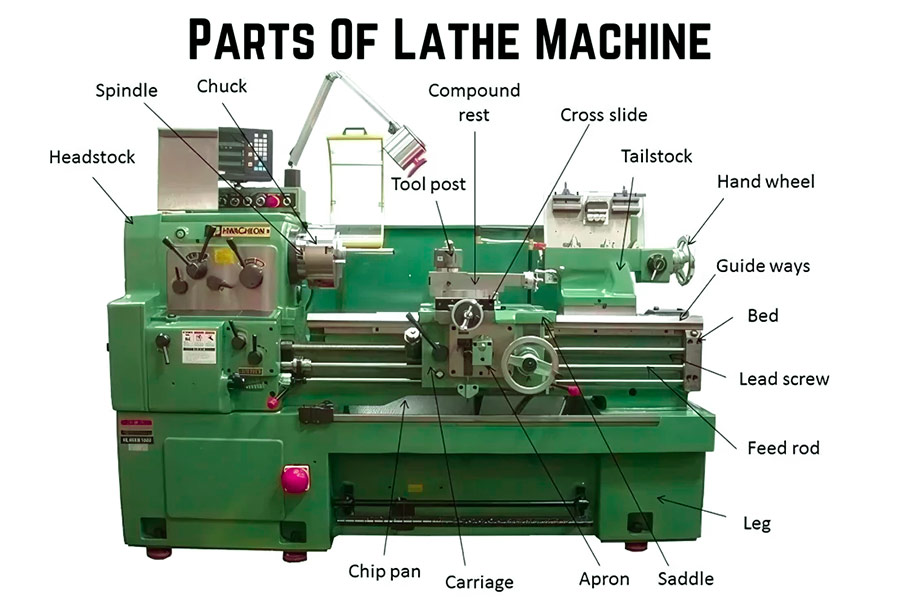
Why Trust Our Guide? We Know Rotation Inside And Out
Hi, I’m Gloria, an engineer at LS. In our custom 5-axis CNC machining, rotation is no small matter—it’s the air we breathe every day. The spindle that drives the tool, the chuck and turntable that carries the workpiece, the precision guide rails, the efficient turrets… Every rotation and positioning of them directly affects the success or failure of micron-level precision. This is our professional instinct.
The authority of this guide comes from our real industrial practice of manufacturing complex 5-axis parts. We not only produce parts, but also understand the core principles behind them—bearings, servo drives, thermal deformation control, and spatial coordinate transformation. It is this hard-core industrial knowledge that enables us to interpret and pay tribute to the exquisiteness of classic woodworking machines (such as lathes and milling machines).
We firmly believe that all great innovations begin with a deep understanding of the basic principles. And “rotation” is one of the most core and exquisite forms of mechanical movement. This guide embodies the sweat and pursuit of the LS team in the field of precision rotation, aiming to take everyone back to the basics and gain insight into the foundation and future potential of precision manufacturing from “rotation”.
Believe in our expertise, let us explore the mystery of rotation together and spin out a more precise future.
The Heart And Brain Of A Lathe: The Headstock
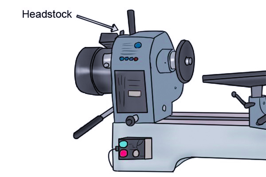
“If a lathe has a heart, it must be the headstock.” This core component located on the left side of the lathe bed is not only the source of power, but also the control center for the rotation accuracy and stability of the workpiece.
A quick overview of the core components of the spindle box
| Component name | Core function | Main features/components |
|---|---|---|
| Headstock | Contains and supports the drive system, providing a rigid foundation | Sturdy box structure, fixed to the left side of the bed |
| Spindle | Transmits rotational motion and power, directly drives the workpiece | High-precision rotary axis, with a clamping device installed at the front |
| Drive System | Provides power and adjusts the spindle speed | Motor, pulley/gear set, speed change mechanism |
| Workholding | Firmly fix the workpiece and rotate with the spindle | Chuck or Faceplate |
1. Headstock:
- Positioning: A solid box on the left side of the lathe bed.
- Core function: To accommodate and support the spindle, bearings and drive components, provide a rigid foundation, ensure rotation stability and precision, and protect the internal mechanism.
2. Spindle:
- Core function: The precision rotating axis in the spindle box is the direct source of workpiece rotation.
- Key features: It is supported by high-precision bearings, connected to the drive at one end, and the clamping device is installed at the other end. Its precision and strength directly affect the processing quality (roundness, finish) and load-bearing capacity.
3. Drive System:
- Function: To transmit power and adjust the spindle speed.
- Composition: It consists of a motor, a transmission mechanism (pulley/belt or gear set) and a speed change mechanism (manual lever, inverter, etc.) to achieve power transmission and speed control.
4. Workholding:
- Function: To firmly clamp the workpiece so that it rotates with the spindle.
- Main types:
- Chuck: (commonly used with three-jaw/four-jaw) clamps the workpiece by radially moving the jaws, universal and convenient.
- Faceplate: A disc mounted on the end face of the spindle, using T-slots/threaded holes with pressure plate screws to fix irregular or large workpieces.
The spindle box is the “heart” and “brain” of the lathe. It carries the precision drive system (power source) and the spindle (rotation core) through its sturdy box, and supports the clamping device (workpiece interface). It is the fundamental basis for ensuring reliable power transmission and precise and stable rotation.
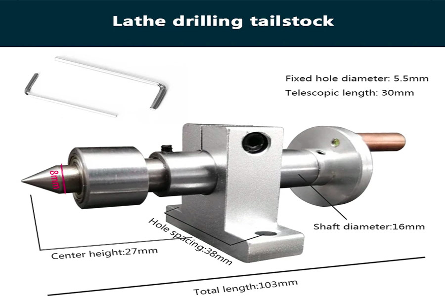
Solid Support: Tailstock
“The spindle box is responsible for driving, while the tailstock is responsible for providing stable support at the other end.”
Core Component Quick View Table:
| Component Name | Core Function and Features |
|---|---|
| Tailstock Body | Can slide along the bed rails and adjust the position to accommodate workpieces of different lengths. |
| Quill | Located inside the body, it can be precisely extended and retracted, with the top installed at the front end. |
| Handwheel | Rotates to drive the top sleeve to extend and retract, controlling the support force on the workpiece. |
| Live Center | A conical top with a bearing, installed at the front end of the sleeve, which can rotate with the workpiece when supporting it, greatly reducing friction and heat generation. |
1. Tailstock Body:
This is the basic structure of the tailstock, usually made of solid cast iron.
Its bottom is designed with grooves or slides that precisely match the guide rails of the lathe bed.
The core function is to allow the entire tailstock to slide manually on the guide rails, so that the operator can adjust the distance between the tailstock and the spindle box according to the length of the workpiece to be processed, so that the tailstock center can accurately support the other end of the workpiece. After adjustment, it is usually firmly locked to the bed with a locking rod or bolt to prevent movement during processing.
2. Quill:
A precision-machined cylindrical sleeve that is nested inside the tailstock body.
It can move back and forth (telescope) smoothly and accurately in the guide hole of the tailstock body.
The core function is to provide the installation position and movement path of the center (usually a live ejector). Through its telescopic movement, the center is pushed into contact with the workpiece and provides support, or withdrawn after processing to remove the workpiece. The sleeve usually has a scale to accurately control the moving distance.
3.Handwheel:
Mounted at the rear of the tailstock body (sometimes on the side), connected to the precision screw mechanism inside.
The operation method is to manually rotate the handwheel.
The core function is to convert the operator’s rotational movement into the linear motion of the top sleeve. Clockwise rotation of the handwheel usually advances the top sleeve and the top to contact and tighten the workpiece; counterclockwise rotation retracts the top sleeve and the top. The handwheel provides the ability to make fine and controllable adjustments to the support force.
4.Live Center:
A key support component installed in the front-end tapered hole (usually Morse taper) of the top sleeve.
Its characteristic is that the tip is tapered (60 degrees or 75 degrees are common) for pushing into the center hole of the workpiece; precision bearings (ball bearings or roller bearings) are installed inside.
The core function is to provide stable support while its tapered tip can rotate freely as the workpiece rotates. The internal bearing greatly reduces the sliding friction between the center center and the workpiece center hole, thereby effectively preventing the workpiece from overheating, burning, excessive wear, and reducing the drive load, which is especially suitable for processing at higher speeds. This is the most essential difference between it and the fixed “dead center”.
The tailstock, through its movable body, precision-adjustable center sleeve, handwheel for control, and live ejector that can rotate with the workpiece, together constitutes a stable, flexible and low-friction rear end support system that is indispensable in lathe processing. It works in conjunction with the spindle box to ensure the rigidity and precision of the workpiece during the rotation process.
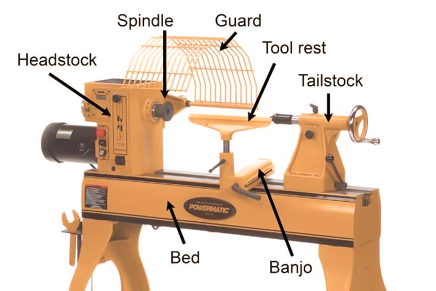
The Guide For Precise Cutting: Carriage/Tool Rest Assembly
“This is the bridge between the turning tool in your hand and the rotating wood.”
At a glance at the core components:
| Component name | Core function | Key operation |
|---|---|---|
| (Tool Rest Base / Banjo) | It provides a base for movement and positioning, and can be freely translated and rotated on the bed. It is named after its shape similar to a banjo. | It is named after its shape similar to a banjo. It is fixed to the desired position on the bed rail by a locking handle. |
| Tool Rest | The horizontal support rod provides a stable and precise fulcrum for the turning tool and is the direct supporting platform for the cutting action. | It is fixed to the base by a locking handle, and the extension length and angle can be adjusted along the base (partial design). |
| Locking Levers | Make sure the tool holder base and the tool holder itself remain absolutely stable in the set position to prevent displacement during cutting. | It is easy to operate and needs to be firmly locked after adjustment to ensure safety and precision. |
1. Tool Rest Base (Banjo):
- Structure and Function: This is the base of the tool rest assembly, usually in a T-shaped or “banjo” shape. Its bottom is designed to match the shape of the lathe bed rail (such as a dovetail groove or V-shaped groove).
- Core Function: It carries the tool rest and allows the operator to slide it forward and backward along the lathe bed to cover different processing areas of the workpiece. More importantly, it can usually rotate a certain angle around the central axis and move left and right after rotation, so as to accurately position the tool rest in the best cutting position on the side of the workpiece.
- Operation: After moving into position, it needs to be firmly fixed to the bed using the locking handle on it.
2. Tool Rest:
- Structure and Function: A straight (or with a specific curve/angle) horizontal metal rod, usually made of high-strength steel. It is vertically mounted on the tool rest base (Banjo) through a pivot or clamping mechanism.
- Core Function: This is the direct support platform and guide reference for the turning tool. The operator holds the turning tool in his hand, and the blade rests on the tool rest. It provides a vital support point and leverage point for the turning tool, allowing the operator to stably and accurately control the cutting depth, angle and direction, resist cutting forces, and prevent the turning tool from being “dragged in” by the workpiece.
- Operation: Its height can usually be adjusted (by loosening the mounting point) to accommodate workpieces of different diameters and different tool operation methods. After adjustment, it needs to be fixed with its own locking handle.
3. Locking handle (Locking Levers):
- Structure and function: It is usually a bolt mechanism with a knob or handle, distributed at the connection between the tool rest base (Banjo) and the tool rest (Tool Rest).
- Core Function: Provides a quick and firm locking force.
- Base locking handle: Locks the tool rest base (Banjo) in a selected position on the bed to prevent it from moving under the action of cutting forces.
- Tool Rest Locking Handle: Locks the tool rest at the selected height and angle on the base to ensure the absolute stability of the tool support point.
- Criticality: The reliability of the locking is directly related to operational safety and machining accuracy. Any looseness may lead to uncontrolled cutting, tool damage or workpiece scrapping.
Comparison with CNC lathes:
In CNC lathes, the manual positioning and support functions of the tool rest assembly are replaced by a more complex turret and servo-driven saddle/cross-slide system. The turret can automatically index and switch multiple tools, while the high-precision servo motor drives the slide to perform automated and precise feed motion along the X-axis (radial) and Z-axis (axial), realizing unattended complex part processing.
Solid Foundation: Bed
“The stable operation of all parts depends on a solid and unchanging foundation.”
| Component name | Core function | Precision influence |
|---|---|---|
| Bed | The main structure of the lathe provides rigidity and shock absorption | The basis of overall stability |
| Ways | Precision machined rails to support the sliding of moving parts | Directly determine the moving accuracy of the tool holder and tailstock |
1. Bed:
This is the most basic and largest component of the lathe, forming the skeleton and foundation of the entire machine.
It is usually cast from heavy cast iron (such as gray cast iron), carefully designed (often with reinforcing ribs inside) and aged.
Its core function is to provide extremely high rigidity (Stiffness), resist the huge force generated during cutting, and prevent deformation; at the same time, the characteristics of cast iron itself give it excellent damping (Damping) performance, effectively absorb vibration, and ensure the stability of the cutting process. It is the reference platform for the installation and movement of all other parts of the lathe.
2. Ways:
Located on the top of the bed, it is a very straight, smooth and parallel (or at a specific angle, such as V-shaped) track surface formed by ultra-precision processing (grinding or scraping).
The key sliding parts of the tailstock and tool holder assembly (including the large and medium carriages, etc.) are installed and run on these guide rails.
The straightness, parallelism and surface finish of the guide rails are one of the most core precision indicators of the lathe. They directly determine whether the motion trajectory of the moving parts (especially the tool holder) is accurate, and then directly determine the processing accuracy that the lathe can achieve (such as the roundness, cylindricity, straightness, etc. of the workpiece). Any wear, scratches or deformation of the guide rails will seriously affect the processing quality.
Importance: “A twisted or uneven bed cannot produce a straight workpiece.” The bed is the absolute foundation of the rigidity and stability of the entire lathe, and the guide rails are the core lifeblood of precision transmission; the two together constitute the “solid foundation” on which the lathe depends, and their quality directly determines the performance limit and processing capacity of the lathe.
Case Analysis: Turning a Baseball Bat – The Art of Collaboration of the Core Components of Machine Tools
Today, I would like to use a classic case – turning a wooden baseball bat to show you how precision machine tools can efficiently complete the processing of complex long-axis workpieces through the perfect collaboration of core components.
Project Core: Processing a typical axisymmetric slender workpiece – a baseball bat, which requires extremely high stability and precise tool guidance.
Collaboration Process Analysis:
- Solid Installation (Spindle Box + Tailstock + Bed): The processing begins with one end of the wood firmly clamped in the chuck of the spindle box (providing rotational power), and the other end is precisely supported by the live ejector of the tailstock. The entire workpiece relies on a solid bed rail to form a rigid reference system to ensure that the long workpiece does not vibrate and deviate at high speed, which is the cornerstone of precision and safety.
- Efficient Roughing (Tool Holder + Spindle Box): The tool holder carries a large round chisel, adjusts it to a position close to the workpiece and finds a stable support point. While the spindle box drives the workpiece to rotate steadily, the tool holder guides the tool to move along the bed rails, quickly and controllably removing most of the excess material and laying the basic outline.
- Fine shaping (dynamic adjustment of the tool holder): As the characteristic contours of the baseball bat (such as the grip, transition area, and bat head) emerge, the operation requires the tool holder to play a key role. We constantly fine-tune its position and angle, and replace more sophisticated turning tools. The precise positioning and flexible adjustment capabilities of the tool holder enable complex surfaces and precise dimensions to be gradually formed.
- Finishing and finishing (tool holder + spindle box, tailstock removed): When the main processing is nearly completed, in order to process the end face of the baseball bat, we flexibly remove the tailstock support. At this time, the tool holder can guide the tool to complete the final end face finishing or detail finishing by clamping only one end of the spindle box, demonstrating the flexibility of system design.
This baseball bat turning case clearly illustrates the perfect coordination of the four core components of the lathe:
- The spindle box is the source of power, driving the workpiece to rotate.
- The bed is the foundation of stability, providing a rigid reference guide for all movements.
- The tailstock is the pillar of support, especially for slender workpieces, providing indispensable auxiliary support to ensure machining rigidity.
- The tool holder is the hand of control, accurately guiding and fixing the tool to achieve material cutting and forming.
At LS, we deeply understand the importance of this precise cooperation between components for machining complex workpieces (such as baseball bats). Our lathe design is centered around ensuring that these core components can work seamlessly, stably and reliably under the most demanding working conditions, ultimately helping users achieve efficient and high-precision machining goals.
From Woodworking To 5-axis: The Eternal Core Of Rotation And Cutting
The core action of wood lathes – workpiece rotation and tool cutting – laid the foundation for all turning technologies. Although materials, drives, precision and complexity have undergone tremendous changes, these two physical principles have been completely inherited and continuously evolved like genes.
Evolution of core principles:
1. Spindle: From single drive to multi-functional core
- Inheritance: Drive workpiece rotation.
- Evolution: The modern milling center spindle has multiple functions, which can drive workpiece rotation (turning) and can also drive rotating tools (milling, drilling, tapping) at high speed like the milling machine spindle. At the same time, it has high power, high rigidity, high precision and C-axis (rotation axis around the spindle) positioning capabilities.
2. Tool holder: From manual support to smart warehouse
- Inheritance: Support and guide tools.
- Evolution: Evolved into an automatic turret, integrating a large number of tools to form a “mobile library” and quickly switching through the automatic tool change system (ATC). The turret is installed on a multi-axis linkage slide (X, Z, and sometimes Y), and cooperates with the spindle C axis to achieve precise positioning of the tool in space.
3. Control: From experience and skills to digital intelligence
- Inheritance: Manual manipulation of tool trajectory.
- Evolution: Replaced by CNC and servo systems. Processing is precisely controlled by the program, driven by servo motors, and cooperates with high-precision feedback elements (grating rulers, encoders) to achieve micron-level precision closed-loop control. The core of 5-axis CNC is to add two rotation axes (B axis: swing around the Y axis; C axis: rotate around the Z axis), so that the tool can approach complex surfaces at the optimal angle, realize multi-faceted one-time clamping processing, and avoid repeated positioning errors.
Value embodiment:
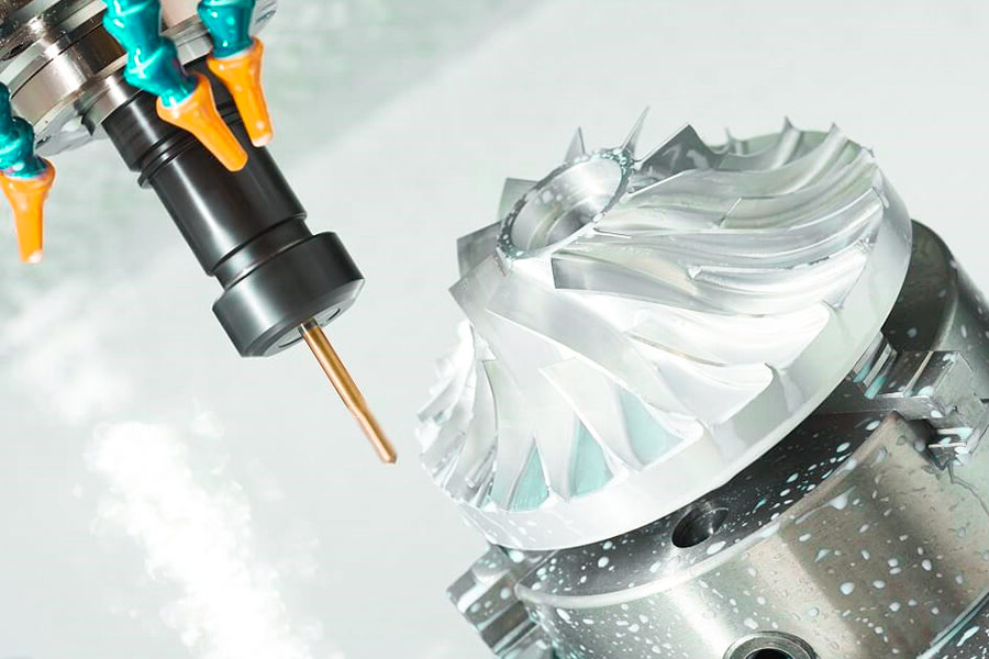
Understanding the core of “rotation” and “cutting” can give you insight into the power of 5-axis CNC: for example, by dynamically adjusting the tool direction through the B/C axis, the twisted blades of the impeller or the complex bionic surfaces of medical implants can be processed efficiently and accurately in one clamping to ensure surface quality.
From the simple woodworking lathe to the exquisite dance of 5-axis CNC, manufacturing technology has undergone tremendous changes. But peeling off the shell of automation, precision control and complex algorithms, the driving core is always the eternal “rotating workpiece” and “cutting and forming”. This deep understanding allows us to remember the source of its power when mastering the top technology, and push the manufacturing boundaries to infinitely extend in the direction of greater precision, complexity and efficiency.
FAQ – Final Question About Lathe Parts
1. What are the main differences between woodworking lathe and metal lathe parts?
The core difference is that metal lathes need to cope with higher cutting forces, so they have stronger rigid structures, greater drive power and higher precision parts. The most significant difference is the feed system: metal lathes are equipped with automatic feed turrets (Power Feed/Apron) driven by gearboxes to achieve precise motorized feeding; while woodworking lathes are usually manually operated by hand tools, with simpler and lighter structures and no need for complex transmission mechanisms.
2. Should I buy a lathe or a tool first?
It is recommended to choose a lathe first. The core parameters of the lathe (such as the maximum swing diameter of the bed “Swing Over Bed” and the distance between the two centers “Center Distance”) directly determine the size range of the workpiece that can be processed, which in turn affects the specifications of the required tool (such as tool holder size, tool bar length). The tool must match the lathe capacity to avoid the tool being unable to be used or the processing range being insufficient due to lathe limitations.
3. What is “Swing Over Bed”?
“Swing Over Bed” refers to twice the vertical distance from the centerline of the lathe spindle to the highest point of the bed rail. It is a key performance indicator that intuitively represents the maximum diameter of the workpiece that the lathe can rotate to process (the height of the tool holder must be considered). For example, the mark “400mm Swing” allows the maximum processing of disc-type workpieces with a diameter of 400mm above the bed. This parameter directly affects the selection of equipment processing capacity.
Master The Names And Open The Door To Excellence
Exploring “What are the various parts of a woodworking lathe called?” is not just about knowing a few terms. The stability of the bed, the drive of the spindle box, the grip of the chuck, the support of the tailstock, the feed of the tool holder, the precision of the guide rails, and even the speed change of the pulley… Behind each component name, there is a century-old mechanical wisdom. They work together to shape the rotating wood into the shape you want. A deep understanding of these “seemingly simple” structures is the first solid step for you to transform from a woodworking enthusiast to a true professional craftsman. These basic principles are not only the soul of wood art, but also the source of inspiration for modern cutting-edge manufacturing (such as 5-axis CNC technology).
When Creativity Goes Beyond Wood, LS Helps You Soar
However, when your design inspiration is no longer satisfied with the boundaries of wood, and you are eager to challenge more complex geometric shapes, pursue higher precision limits, or need stronger materials such as metal to realize your ideas, you need more powerful tools. LS’s online 5-axis CNC machining service is the ideal extension platform for your creativity. No complicated local equipment is needed, just upload your CAD file immediately to get an instant 5-axis CNC machining price. Let us use the top industrial-grade precision and omnipotent processing capabilities to elevate your design concept that originated from woodworking but has surpassed wood to an unprecedented new height! [Experience LS 5-axis CNC now and make your manufacturing dream come true! ]
 📞 Phone: +86 185 6675 9667
📧 Email:info@longshengmfg.com
🌐Website:https://www.longshengmfg.com/


hello there and thank you for your info – I’ve certainly picked up something new from right here. I did however expertise a few technical issues using this web site, as I experienced to reload the site many times previous to I could get it to load correctly. I had been wondering if your web hosting is OK? Not that I am complaining, but slow loading instances times will often affect your placement in google and could damage your high-quality score if ads and marketing with Adwords. Well I’m adding this RSS to my e-mail and can look out for much more of your respective fascinating content. Ensure that you update this again soon..
Chairlyn, thank you so much for your detailed and thoughtful feedback! First of all, we’re delighted that you found something new and useful here. Secondly, the issues you mentioned regarding loading and reloading are extremely important; I will immediately investigate the website performance and server status. Thank you for pointing this out. We also appreciate you adding us to your RSS feed; this shows great trust in our content! We will optimize the user experience as soon as possible. Thank you again for your help!
Thank you for another informative web site. Where else could I get that type of information written in such an ideal way? I’ve a project that I’m just now working on, and I’ve been on the look out for such info.
I will right away grab your rss as I can’t to find your e-mail subscription hyperlink or newsletter service. Do you’ve any? Kindly let me know in order that I may subscribe. Thanks.