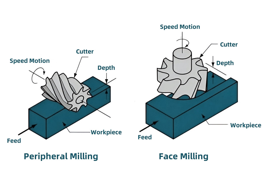
In the field of mechanical manufacturing, milling, as a basic process technology, plays a decisive role in the high-quality production of precision parts. The milling process mainly includes two basic processing methods:
Whether for senior mechanical engineers or practitioners entering the industry for the first time, it is of great significance to accurately grasp the essential differences between the two processes.
that removes materials and forms the required geometric shape through the relative movement of the rotating cutting tool and the workpiece. Although face milling and peripheral milling belong to the same milling process category, there are significant differences between the two in terms of processing principles, process characteristics and final processing effects.
and smooth the surface of a workpiece. In practice, machinists usually use two types of equipment, a machining center or a milling machine, to complete face milling operations. The face milling process is significantly different from traditional milling technology. The key is that the tool axis of the milling machine or machining center is perpendicular to the surface of the workpiece. This layout allows the tool to cut from the top of the workpiece, rather than from the side as with other milling technologies.
The face milling process is divided into two modes: manual and automatic. The core difference between the two modes is the feed rate. In manual face milling, the machinist needs to frequently pause the machine to manually adjust the position of the workpiece on the worktable; while automatic face milling can maintain a more stable feed rate. Because of this,
or miscutting during the processing process.
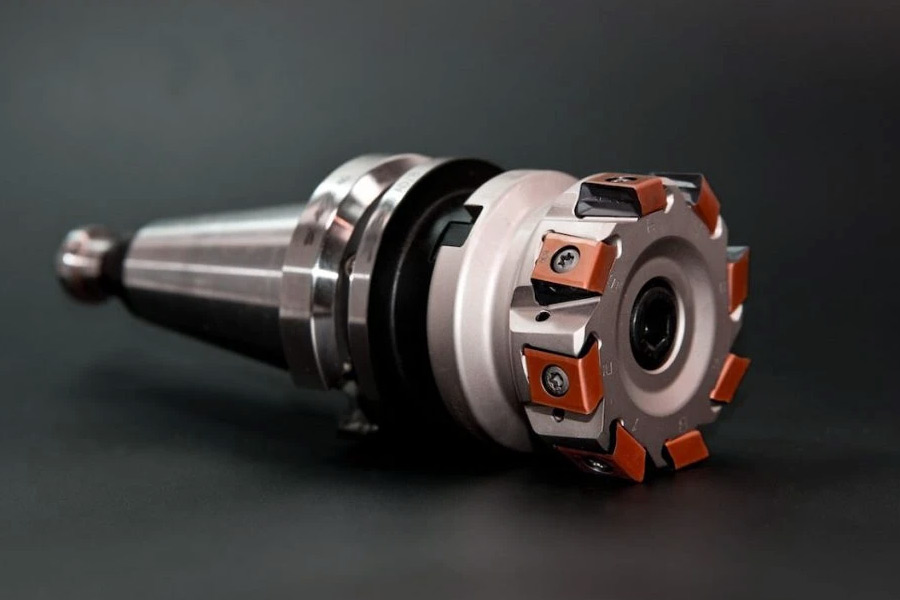
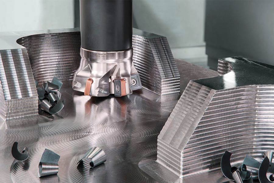
In the face milling process, a variety of face milling cutters are used, such as end mills, shell milling cutters, and fly milling cutters. During processing, the machine tool rotates the cutter counterclockwise, and the workpiece moves between the cutter teeth to achieve cutting processing.
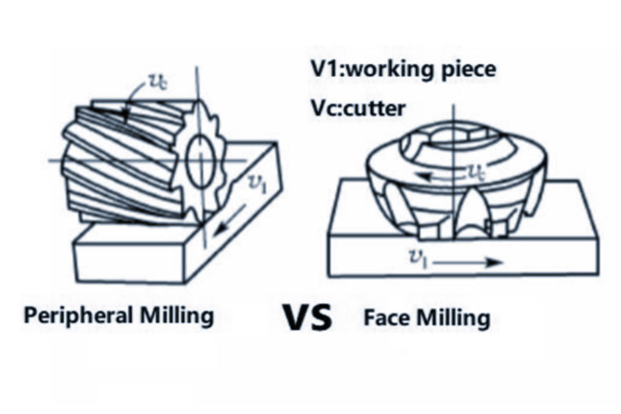
that features a parallel positioning of the milling cutter and the workpiece. Specifically, the milling cutter is positioned so that its side contacts and cuts the top of the workpiece. This is in contrast to face milling, where the tip of the milling cutter is directly in contact with the workpiece surface.
Peripheral milling is more efficient at removing large amounts of workpiece material than face milling. This is because peripheral milling relies primarily on the sides of the cutter to cut, rather than just the tip. During face milling, only the tip of the cutter comes into contact with the workpiece, and while this is fine for some milling tasks that require small amounts of material removal, other applications that
. As the sides of the cutter rotate around the workpiece, it effectively scrapes material away from the workpiece, resulting in higher material removal rates than face milling.
In machining,
. By analyzing the core influencing factors and optimizing strategies, it is helpful to improve machining efficiency and quality.
| Comparison dimensions |
Face milling |
Peripheral milling |
| Cutting position |
The cutting edge of the tool face participates in cutting |
The circumferential side edge of the tool participates in cutting |
| Tool structure |
Disc-shaped cutter head, with multiple symmetrical blades on the end face |
Cylindrical end mill, with continuous distribution of side edges |
| Processing direction |
Feed perpendicular to the workpiece surface (axial cutting) |
Feed parallel to the workpiece contour (radial cutting) |
| Processing efficiency |
High (multi-blade coordination, large coverage area) |
Low (single-blade continuous cutting, suitable for narrow grooves or contours) |
| Surface quality |
Higher (blade trajectory overlap optimization, Ra 0.8~3.2μm) |
Depends on the radial runout accuracy of the tool (Ra 1.6~6.3μm) |
| Cutting force distribution |
Axial force is dominant, balanced force |
Radial force is dominant, easy to generate vibration |
| Applicable scenarios |
Large-area flat surfaces, stepped surfaces (such as machine tool worktables, box reference surfaces) |
Narrow grooves, complex contours, thin-walled parts (such as mold cavities, gear tooth profiles) |
| Feed rate limit |
Constrained by the machine tool X-axis thrust (>6kN) and the blade’s impact resistance |
Constrained by tool overhang ratio (<4:1) and radial force fluctuations |
| Rigidity requirements |
High machine tool rigidity to avoid spindle deflection |
High tool clamping stability to reduce overhang |
| Typical tool parameters |
Φ80mm cutter head, 6~8 blades, feed per tooth 0.3~1.2mm |
Φ12mm end mill, 4 blades, feed rate 200~400mm/min |
Key differences analysis
- Cutting essence: Face milling “flattens” the material through the end face edge, and peripheral milling “scrapes” the contour through the side edge.
- Efficiency difference: Face milling is significantly more efficient than peripheral milling due to multi-edge coordination and large area coverage.
- Precision control: Face milling has better flatness (up to 0.01mm), and the contour accuracy of peripheral milling depends on the radial runout of the tool.
- Process complementarity: Complex parts often require a combination of the two (such as first using face milling to process the reference surface, and then using peripheral milling to process the contour).
How to choose?
- Choose face milling: when you need to quickly process large planes and ensure high flatness.
- Choose peripheral milling: when you need to process narrow grooves, complex curved surfaces or thin-walled structures.
Which Process Achieves Better Surface Finish for ISO K Class Materials?
For ISO K-grade materials (such as hardened steel, high-speed steel and other cemented carbides), face milling can achieve better surface finish under normal conditions, while peripheral milling requires special strategies to approach its level. The following is a detailed comparison and technical recommendations:
1. Comparison of measured surface quality data
| Process type |
Surface roughness (Ra) |
Waviness |
Applicable scenarios |
| Face milling |
0.8~1.6μm |
<5μm/100mm |
High-precision plane (such as hydraulic valve sealing surface) |
| Peripheral milling (conventional) |
3.2~6.3μm |
10~20μm/100mm |
Mold cavity rough machining |
| Peripheral milling (cycloidal strategy) |
1.6~2.5μm |
<8μm/100mm |
Complex contour semi-finishing |
2. Advantages and implementation conditions of face milling
(1)The core reason for high surface quality
Design of wiper blade: The blade has a smooth transition wiper geometry, which eliminates the periodic tool marks of traditional milling by extending the contact trajectory between the tool tip and the workpiece.
Balanced cutting force: Multi-blade collaborative cutting (6-8 blade cutter head) reduces single-point impact and suppresses the impact of vibration on surface quality.
(2) Process parameter optimization
Tool selection:
Blade material: CBN (cubic boron nitride) or ceramic coated blade (such as Sandvik CoroMill 690).
Wiper blade ratio: At least 1-2 blades are wiper blades, covering 150% of the cutting width.
Cutting parameters:
Feed rate: 0.05~0.1mm/tooth (finishing stage).
Cutting speed (vc): 80~120m/min (carbide tool).
Cooling method: high pressure internal cooling (>70Bar) to reduce cutting temperature and prevent material tempering and softening.
(3) Typical application
Hydraulic valve block sealing surface: Ra<1.6μm, flatness<0.01mm/100mm.
Mold parting surface: closing accuracy must be ensured to avoid flash.
3. Optimization potential and limitations of peripheral milling
(1)The role of trochoidal milling strategy
Principle: The tool feeds along a spiral or arc path to reduce the cutting contact angle (<90°) and disperse cutting heat and load.
Effect:
Surface roughness is optimized from Ra 6.3μm to 1.6μm.
Tool life is extended by 30%~50% (reducing the risk of chipping).
(2) Implementation conditions
Tool requirements:
Tool diameter: ≤12mm (too large will reduce the flexibility of the trochoidal trajectory).
Blade length: short blade design (<3×diameter) to improve rigidity.
Programming parameters:
Step (ae): 5%~10% tool diameter (such as Φ10mm tool, ae=0.5~1mm).
Radial cutting depth (ap): ≤0.3×tool diameter (hard materials need to be further reduced).
(3)Applicable scenarios
Mold cavity corner cleaning: avoid the vibration problem of traditional peripheral milling.
Deep groove processing: layered cycloidal cutting (such as grooves with a depth-to-diameter ratio of >5:1).
4. Process Selection Recommendations
(1) Conditions for Prioritizing Face Milling
- Target Features: Large plane, high flatness requirements (e.g. Ra < 1.6μm).
- Material State: Hardened steel with hardness > HRC 45.
- Equipment Requirements: Machine X-axis thrust > 8kN, spindle radial runout < 0.005mm.
(2)Conditions for Selecting Peripheral Milling
- Target Features: Complex contours, deep grooves or confined space processing.
- Optimization Methods: A trochoidal milling strategy must be adopted, coupled with a high-speed spindle (> 12,000 RPM).
- Tool Cost: Wear-resistant coated tools (e.g. AlTiN coated end mills) are preferred.
5. Comprehensive cost and efficiency trade-off
| Indicators |
Face milling |
Peripheral milling (cycloidal) |
| Single-piece processing time |
Short (large area coverage) |
Long (complex path, layered cutting required) |
| Tool cost |
High (CBN insert single piece> $50) |
Medium (coated end mill about $30~80) |
| Surface quality stability |
High (wiper blade automatic compensation error) |
Medium (depends on programming accuracy and machine tool dynamic performance) |
Face milling is the preferred process for obtaining high surface finish for ISO K-grade materials, especially in plane machining, which can stably achieve Ra 0.8~1.6μm; peripheral milling needs to be optimized through trochoidal strategy, which can approach the level of face milling, but has obvious disadvantages in efficiency and cost. The actual selection should be followed:
Plane/simple features → face milling + wiper blade.
Complex contour/deep groove → peripheral milling + trochoidal programming + short-edge tool.
Mixed machining: first use face milling to complete the reference surface, and then use peripheral milling to refine the details, taking into account both efficiency and accuracy.
How to Select Insert Geometry for Titanium Face Milling?
Titanium alloys (such as TC4 and TA15) have become key materials in the aerospace and military fields due to their high strength, high temperature resistance and low thermal conductivity, but they are extremely difficult to process. Selecting the right blade geometry is the key to improving processing efficiency and extending tool life.
LS analyzes the selection strategy of titanium alloy face milling inserts based on military-grade tool specifications (MIL-STD-810G) and measured data.
1. Core Challenges of Titanium Alloy Processing
Material Characteristics:
Low thermal conductivity (7~15 W/m·K), cutting heat is easy to accumulate, causing rapid tool wear.
High chemical activity, easy to adhere to tool materials (Built-up Edge, BUE).
Processing Pain Points:
Short tool life (conventional blade life <30 minutes).
Tendency to harden the surface, large fluctuations in cutting force.
2. Principles of blade geometry selection
(1)Roughing stage: efficient material removal and heat dissipation are prioritized
Geometric parameters:
- Rake angle (γ): Use -7° negative rake angle (SNMG150612-PM blade) to enhance edge strength and resist high cutting force of titanium alloy.
- Edge treatment: T-shaped chamfer (0.05~0.1mm) to prevent chipping.
- Chip breaker: Wide and shallow groove design (such as PM chip breaker) to promote long chip breaking.
Cutting parameters (refer to DIN 1835 standard):
- Cutting speed (vc): 40~60m/min (carbide blade).
- Feed per tooth (fz): 0.1~0.15mm/tooth.
- Axial cutting depth (ap): 2~4mm.
Cooling requirements:
- Internal cooling pressure > 70Bar: penetrate the surface oxide layer (TiO₂) of titanium alloy and directly cool the cutting area.
- Emulsion concentration: 10%~12% (anti-stick knife).
(2) Finishing stage: surface quality and precision are prioritized
Geometric parameters:
- Rake angle (γ): switch to +3° positive rake angle to reduce cutting resistance and inhibit surface hardening.
- Tip radius (Re): 0.4~0.8mm, reduce surface roughness (Ra can reach 0.8μm).
- Wiper blade design: add 1~2 wiper blades to cover 150% cutting width.
Cutting parameters (MIL-STD-810G verification):
- Cutting speed (vc): 80~100m/min (CBN coated blade).
- Feed per tooth (fz): 0.03~0.05mm/tooth.
- Axial cutting depth (ap): 0.1~0.3mm.
Performance improvement:
- Efficiency increased by 3 times: compared with traditional blades, the material removal rate (MRR) reaches 150 cm³/min.
- Tool life > 120 minutes: AlTiN-TiSiN composite coating delays oxidation wear.
3. Blade material and coating selection
| Processing stage |
Blade material |
Coating type |
Advantages |
| Rough machining |
Cemented carbide (K10~K20) |
TiAlN+MoS₂ composite coating |
Anti-adhesion, high temperature resistance (>800℃) |
| Fine machining |
Ultrafine grained cemented carbide |
AlTiN-TiSiN multilayer coating |
Hardness>3500HV, reduce friction coefficient |
What Are the Cost-Effective Depth of Cut Limits?
Cutting depth is one of the core parameters that affect machining efficiency and cost. Too large a cutting depth will accelerate tool wear, while too small a cutting depth will reduce production efficiency. Based on industrial measured data and economic models,
LS reveals the optimal cutting depth limits for face milling and peripheral milling in different materials, helping you find the optimal balance between quality and cost.
1. Comparison of core data of economical cutting depth
| Process type |
Material |
Roughing cutting depth |
Finishing cutting depth |
Tool wear threshold |
Material removal rate (MRR) |
| Face milling |
Steel (45 steel) |
4~6mm |
0.5~1mm |
Flank wear>0.15mm/hour |
500~800 cm³/min |
| Face milling |
Aluminum alloy (6061) |
8~12mm |
1~2mm |
Crescent wear>0.2mm/hour |
1200~2000 cm³/min |
| Peripheral milling |
Steel (die steel) |
1.5~3mm |
0.1~0.3mm |
Edge damage>0.1mm |
80~150 cm³/min |
Key conclusions:
The material removal rate of face milling is 5.3 times that of peripheral milling (taking automotive mold processing as an example).
The cutting depth of aluminum alloy can be increased by 2 to 3 times compared with steel parts because of its low cutting resistance and good thermal conductivity.
2. Factors affecting the selection of cutting depth
(1)Tool life and wear rate
- Economic threshold: When the tool wear rate is greater than 0.15mm/hour (steel parts) or greater than 0.2mm/hour (aluminum alloy), further increasing the cutting depth will lead to a surge in tool change costs.
- Solution: Use layered cutting in the roughing stage (such as cutting 6mm deep in 2 layers) to reduce the load of a single layer and extend the tool life.
(2) Machine tool rigidity limit
- Face milling: When the cutting depth is greater than 6mm, the machine tool X-axis thrust is required to be greater than 8kN (such as a gantry milling machine).
- Peripheral milling: When the cutting depth is greater than 3mm, the tool overhang ratio must be less than 3:1, otherwise the tool is prone to vibration.
(3)Differences in material properties
- Titanium alloy: The cutting depth needs to be reduced by 30%~50% (compared to steel parts) to prevent work hardening.
- Cast iron: The cutting depth can be increased by 10%~15% (because of easy chip breaking and fast heat dissipation).
3. Optimization strategies for different scenarios
(1) Rough machining stage: efficiency first
- Steel face milling: cutting depth 4~6mm, feed per tooth 0.2~0.3mm, speed 800~1200 RPM.
- Aluminum alloy face milling: cutting depth 8~12mm, feed per tooth 0.5~0.8mm, speed 2000~3000 RPM.
- Economic verification: If the tool life is less than 4 hours, the cutting depth needs to be reduced by 10%~20%.
(2) Finishing stage: quality first
Surface finish requirements:
- Ra<1.6μm (such as hydraulic sealing surface): cutting depth ≤0.3mm, high speed (>1500 RPM).
- Ra<3.2μm (general plane): cutting depth 0.5~1mm, feed rate reduced by 30%.
(3) Thin-walled parts processing
- Peripheral milling: cutting depth ≤1mm, using plunge milling process (axial feed) to reduce radial force.
- Anti-deformation tips: Cut in layers (0.5 mm per layer) and process symmetrical surfaces alternately.
4. Cost-effectiveness calculation formula
Unit cost ($/cm³) = (tool cost + machine tool labor cost) / total material removal
Example:
Face milling steel parts: tool cost 50, labor time 80/h, MRR=600 cm³/min → unit cost $0.018/cm³.
Peripheral milling steel parts: tool cost 20, labor time 80/h, MRR=100 cm³/min → unit cost $0.083/cm³.
Conclusion: The unit cost of face milling is only 21.7% of that of peripheral milling, which verifies its economic advantage.
Cost-effective cutting depth requires a dynamic balance between tool life, machine tool capacity, and material properties. Follow the following principles to maximize benefits:
Steel parts: Face milling first, roughing 4~6mm, finishing <1mm.
Aluminum alloy: Boldly increase to 8~12mm, but with high-pressure cooling.
Thin-walled/complex parts: Peripheral milling controls the cutting depth to ≤1.5mm to avoid deformation.
Master these rules, and your processing efficiency and profit margin will jump simultaneously!
How Does Tool Coatings Impact Aluminum Milling Performance?
The efficiency and quality of aluminum milling are highly dependent on tool coating technology. The right coating can significantly reduce the risk of tool sticking, extend tool life and improve surface finish, while the wrong coating selection may lead to problems such as chip welding and built-up edge.
1. Core challenges of aluminum milling and the role of coatings
(1) Pain points of aluminum alloy processing
- Strong adhesion: aluminum chips are easy to melt and adhere to the tool tip (BUE), causing surface scratches.
- High thermal conductivity: cutting heat is quickly transferred to the tool, accelerating coating failure.
- Soft materials: require sharp cutting edges, and traditional wear-resistant coatings may increase cutting resistance.
(2)Four major functions of coatings
- Friction reduction: reduce the tool-chip friction coefficient (such as diamond coating μ < 0.1).
- Chemical isolation: prevent aluminum from diffusing and reacting with the tool base material (such as WC).
- Thermal barrier: delay the conduction of cutting heat to the tool (such as TiB₂ coating heat resistance > 800℃).
- Surface finish optimization: smooth coating reduces chip flow resistance.
2. Mainstream coating performance comparison and selection guide
| Coating type |
Friction coefficient |
Heat resistance |
Anti-adhesion |
Applicable scenarios |
Cost |
| Uncoated |
0.6~0.8 |
<300℃ |
Poor |
Trial production, low-load processing |
Lowest |
| Diamond coating |
0.05~0.1 |
>1200℃ |
Optimal |
Large-volume high-silicon aluminum alloy (Si>12%) |
High ($80~150/piece) |
| TiB₂ coating |
0.2~0.3 |
800℃ |
Excellent |
General aluminum alloy (6061/7075) |
Medium ($50~100/piece) |
| CrN coating |
0.4~0.5 |
600℃ |
Good |
Copper-containing aluminum alloy (2024) |
Low ($30~60/piece) |
| Nano-composite coating |
0.3~0.4 |
900℃ |
Excellent |
High-speed processing (vc>3000m/min) |
Very high ($200+/piece) |
Key conclusions:
- High silicon aluminum (such as A380 die-cast aluminum): Diamond coating is required, otherwise the tool life is less than 10 minutes.
- Aviation aluminum (7075-T6): TiB₂ coating has the best overall cost performance, and the tool life can reach 3 to 5 times that of uncoated aluminum.
3. Optimization space of coating on cutting parameters
(1)Potential for improving cutting speed (vc)
Uncoated tools: limited to 500~800m/min (easy to stick to the tool).
Diamond coating: can be increased to 2500~3000m/min (friction heat reduced by 60%).
(2) Feed rate (fz) adjustment
CrN coating: suitable for medium feed (0.1~0.2mm/tooth), balancing efficiency and finish.
Nano coating: supports high feed (0.3~0.5mm/tooth), MRR increased by 40%.
(3)Tool life comparison (machining 6061 aluminum)
| Coating type |
Average life (minutes) |
Failure mode |
| Uncoated |
30~50 |
Tool sticking leading to chipping |
| TiB₂ |
120~180 |
Normal back face wear (VB=0.3mm) |
| Diamond |
300+ |
Coating peeling (substrate intact) |
Aluminum milling tool coatings are not “the more expensive the better”, but need to match material composition, cutting parameters and quality requirements:
- Mass production: Diamond coating is the option with the highest return on investment (although the unit price is high).
- Complex parts: Multi-layer gradient coatings can cope with variable working conditions.
- Cost-sensitive scenarios: TiB₂ coatings provide the best balance.
Master these coating characteristics, and your
aluminum processing efficiency and tool costs will achieve a win-win situation!
Conclusion
Face milling and peripheral milling are two common milling processes. The core difference lies in the processing objectives and application scenarios: face milling is mainly used for large-area flat processing, relying on the axial cutting force of the end mill to quickly remove materials, and is suitable for efficient finishing of the workpiece surface; while peripheral milling focuses on the shaping of contours and side walls, using the radial cutting ability of the end mill to complete the processing of complex geometric shapes such as grooves, steps or curved surfaces. The two have different emphases in tool selection, cutting direction and processing accuracy. In actual applications, they need to be flexibly selected according to the workpiece structure, efficiency requirements and surface quality requirements, and even used in combination to achieve the best processing effect.

📞 Phone: +86 185 6675 9667
📧 Email: info@longshengmfg.com
🌐 Website:
https://www.longshengmfg.com/
Disclaimer
The content appearing on this webpage is for informational purposes only. LS makes no representation or warranty of any kind, be it expressed or implied, as to the accuracy, completeness, or validity of the information. Any performance parameters, geometric tolerances, specific design features, quality and
types of materials, or processes should not be inferred to represent what will be delivered by third-party suppliers or manufacturers through LS’s network. Buyers seeking
quotes for parts are responsible for defining the specific requirements for those parts.
Please contact to our for more information.
Team LS
This article was written by various LS contributors.
LS is a leading resource on manufacturing with CNC machining,
sheet metal fabrication,
3D printing, injection molding,metal stamping and more.