Do you automatically see a classic image of a cutting edge whirling around at high velocity, cutting through metal and generating sparks when you hear “milling”? This mental image transports you to the definition of milling—the elimination of material with a rotating tool. But have you ever stopped to think that the seemingly lone operation can really be divided into several distinct plain categories of operations, depending on how the tool touches and moves relative to the part?
Many people confuse “types of milling” with “types of milling machines” (like vertical milling machines vs. horizontal milling machines), or with some woodworking terminology. This book is a try at showing you this very important distinction. Rather than a study of the machine, we will consider the core functions of modern CNC milling. Specifically, we will reveal the three most vital and basic types of milling that are employed as the basis for manufacturing most complex components.
Comparison Of Key Characteristics Of Types Of Milling
| Type of Milling | Cutter Axis | Primary Use | Common Cutters |
|---|---|---|---|
| Face Milling | Perpendicular to surface | Create large flat, smooth surfaces. | Face Mills, Shell Mills |
| Peripheral Milling | Parallel to surface | Process edges, steps, grooves and contours of parts. | End Mills, Slot Drills |
| Profile Milling | Variable | Create complex 3D surfaces, chamfers and contours. | Ball End Mills, Bull Nose Mills |
Here’s What You’ll Learn:
- A concise framework to assist you in determining the most suitable type of milling (face milling, peripheral milling, contour milling) for your part needs within 60 seconds.
- The most important distinctions in tool orientation, working principles and machining objectives of the three main milling types (face milling, peripheral milling, contour milling), and how these distinctions influence directly the accuracy of parts, surface finish and realization of intricate geometries.
- Advanced processing technologies for complex 3D components (like drone brackets), uncovering how to blend the three types of milling to get the ideal conversion from blank to finished product.
- Real case study from CNC milling experience, illustrating how the three milling types complement one another to produce high-performance parts and reduce costs (CNC milling expenses).
- Milling type FAQs, climb/conventional milling comparison (climb milling vs. conventional milling), 3-axis/5-axis selection, illustrating the most important concepts.
And now, let’s be more specific about these three building block processes of contemporary manufacturing and learn the important details required to choose the best milling method for your project.
What is Milling? A Building Block Overview
| Points | Description | Key Points |
|---|---|---|
| Core Definition | A manufacturing process that uses a rotating, multi-edged tool to remove material from the surface of a workpiece to shape a part. | The tool is rotated to remove material. |
| The Role of CNC | Computers precisely control the tool path based on a digital model (CAD file), achieving high accuracy and repeatability. | Digital control is the key to the manufacture of complex CNC milled parts. |
| Basic Components | A rotating tool + a workpiece table/fixture that moves in multiple directions. | The relative motion of the tool and the workpiece produces unlimited geometric shapes. |
1. Core definition
Milling is maybe the most basic and common machining process. It consists of its nature in using a cylindrical, high-speed rotating tool or an advanced multiple-edged (toothed) cutting edge tool. The rotating tool is pressed against a moving or stationary workpiece, and its cutting edge continuously cuts into material, removing material in the shape of chips, thereby machining slowly the desired shape, plane, groove, hole or complex contour.
2. The role of CNC:
- Computer drive: Produce parts based on CAD models.
- Automation control: CAM software converts design into G-code instructions.
- Precise execution: CNC machines accurately regulate tool motion (speed, feed) and workpiece table motion (X, Y, Z axis, etc.).
- Major strengths: Achieve high precision, consistency, and repeatability, and can create very complicated CNC milling pieces (cnc milling pieces).
3. Basic components:
- Rotary cutting tool: Provides the main cutting power.
- Movable Table/Fixture: Supports the workpiece and may be precisely positioned and moved in a number of axes (X, Y, Z, and at times A, B, C).
- Synergy: Precise coordination among tool rotation and workpiece movement.
- Core Capabilities: This combination provides unforeseen flexibility to create essentially any desired 2D or 3D shape.
Milling efficiently removes material by precisely coordinating the rotating tool with the moving workpiece, creating anything from a simple flat surface to a highly complex 3D part.
Type 1: Face Milling – Pursuing the Ultimate Flatness
Face milling, like “precision cutting” in the industrial field, is the first key step in establishing a flat benchmark for workpieces.
Face Milling Core Features Quick Reference Table
| Features | Description |
|---|---|
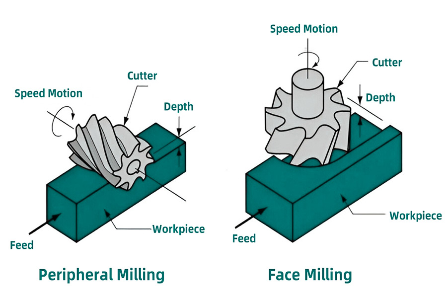
| Working Principle | The tool axis of rotation is perpendicular to the surface being machined, like a large razor scraping across the workpiece surface. |
| Main Goals | 1. Quickly and efficiently remove large amounts of material. 2. Obtain high-quality, high-flatness, smooth surfaces. |
| Typical Applications | Top surfaces of engine blocks, mold bases, mechanical mounting surfaces, and any surfaces that require precision fit. |
| Tool Features | Large diameter, multi-edge milling cutter discs. |
| Processing Features | Usually the first step in the workpiece machining process (roughing or semi-finishing flat surfaces). |
1. Working principle:
The milling cutter disc is equipped with multiple indexable blades (carbide or ceramic), and its rotation axis is strictly perpendicular to the surface of the workpiece to be processed. Through the rotation of the milling cutter disc and the feed movement of the machine tool table (or spindle head), the blades cut the workpiece surface material in sequence.
2. Main goals:
The core advantage lies in its high efficiency, which can quickly mill off a large amount of excess on the surface of the blank (rough milling). At the same time, through precise machine tools, suitable tools and optimized cutting parameters, it can directly process high-flatness, low-surface-roughness precision planes (fine milling), providing precise references for subsequent processes or assembly.
3. Application examples:
The application is extremely wide, covering almost all areas that require large-surface processing. For example: processing the top/bottom surface of the engine block or cylinder head to ensure sealing; processing the base of large molds to ensure stable installation; processing the mounting platform or joint surface of various mechanical equipment to achieve precision assembly; removing the skin or flash of steel plates, castings, and forgings to obtain a flat reference surface.
4. Processing significance:
As one of the most common initial processing procedures, the precise plane established by face milling is the basis for the processing accuracy and assembly quality of the entire workpiece.
Face milling has become an indispensable “opening up” tool in modern mechanical processing with its dual ability to efficiently remove materials and create high-quality reference planes.

Type 2: Peripheral Milling – Finely Crafted Edges and Grooves
If face milling is “opening up new territory”, then peripheral milling is like a precision sculptor, focusing on shaping the edge contours and grooves of the workpiece.
Overview of the key points of peripheral milling
| Features | Description |
|---|---|
| Working Principle | The axis of rotation of the tool is parallel to the surface being machined, and the cutting work is mainly completed by the blade on the circumferential side of the tool. |
| Main Goals | 1. Machining the vertical side walls and step surfaces of the workpiece. 2. Milling grooves, keyways or cavities. 3. Perform contour milling to machine the outer edges of specific shapes. |
| Typical Operations | Side Milling: Machining vertical side walls. Slotting: Milling grooves/keyways (groove width ≈ tool diameter). Slab Milling: Using wide cylindrical milling cutters for large-area machining (mostly seen in horizontal milling). |
| Typical Applications | Machining the side and steps of parts, opening heat dissipation grooves/keyways, finishing the side walls of mold cavities, and cutting contour shapes (such as panels and cams). |
| Tool Features | End mills are typical representatives, cylindrical with peripheral blades, and a variety of size options. Cylindrical milling cutters are often used for plane milling. |
| Machining Features | Good at finishing edges, grooves and contours, and can achieve high dimensional accuracy and shape accuracy. |
1. Working principle
The nub of peripheral milling is that the axis of rotation of the tool (e.g., an end mill) is along the machined surface of the workpiece. The cutting force is mainly on the peripheral edge of the cylindrical surface of the tool, and the work material is removed by tool rotation and axial/radial feed motion. This is just the opposite of the “end face cutting” of face milling.
2. Main objectives and subcategories:
- Side milling: Using the edge of tool periphery to face the vertical side or step surface of the workpiece is a main operation for cutting the part shape and height dimensions.
- Slotting: Inserting the entire width of the side edge of the tool into the workpiece, slotting a groove (e.g., keyway, heat dissipation groove) whose width is about equal to or greater than the tool diameter. Full slot milling involves both sides of the tool in concurrent cutting.
- Slab milling: A special peripheral milling, usually using a broad cylindrical milling cutter (which is often simply called a “corn milling cutter”) in a horizontal milling machine, its periphery being used to mill a larger plane surface parallel to the tool axis. The efficiency is lower than that of face milling, but it is still used in horizontal milling or on special occasions.
3. Application examples:
Extremely wide application and focus on “shaping”:
- Cutting thin heat dissipation grooves in electronic device casings or radiators.
- Treatment of step surfaces and mounting surface side walls of mechanical parts.
- Keyway cutting on shaft parts.
- Accurate cutting of the outer contour of plates or blocks (contour milling).
- Finishing mold cavity side walls.
4. Tools and processing:
End mills are the most universal and extensively used peripheral cutting mills, with many types (flat bottom, ball head, round nose) and types. Contour accuracy, side wall verticality/finish, and groove dimensional accuracy during processing draw more attention.
Peripheral milling is today an inevitable precision shaping process to accurately cut workpiece edges, grooves and complex contours due to its specific approach of paralleling the tool axis to the processing surface.
Type 3: Profile Milling – Shaping a Complex 3D World
Whereas face milling produces a simple plane and peripheral milling outlines the edge groove, profile milling is like drawing out the complex curved world freely on metal with the “3D brush” of a CNC machine tool.
Synopsis of the most significant points of profile milling
| Features | Description |
|---|---|
| Working Principle | Complex combination technique: Combining face milling and peripheral milling, the tool moves along the preset 3D space path to cut non-planar and complex geometric surfaces. |
| Core Goal | Accurately process complex 3D contours, free-form surfaces, and cavities to achieve high geometric accuracy and surface quality. |
| Core Tool | Ball End Mills is the protagonist. Its hemispherical end can smoothly transition, cut surfaces of arbitrary curvature, and reduce step marks. |
| Processing Features | Highly dependent on CNC programming and multi-axis linkage (especially more than 3 axes). Gradually approach the final shape through multi-path layer cutting. |
| Typical Applications | Automotive cover molds, aircraft engine blades, injection/die-casting model cavities, medical device implants, complex curved artworks, turbine impellers. |
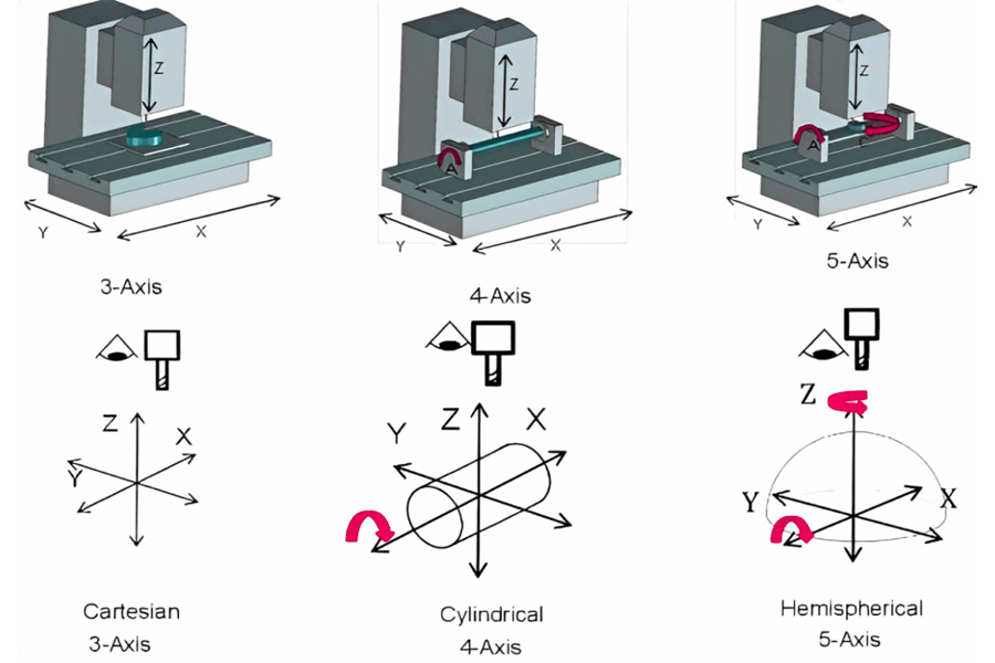
| Key Equipment | 3-axis, 4-axis, and 5-axis CNC machining centers are the core platforms for achieving complex contour milling. |
1. Working principle:
The heart of contour milling lies in the spatiality and intricacy of the tool path. The CNC machine accurately calculates the spatial path by which the tool (primarily the ball end mill) has to travel as computed from the 3D CAD part model in order to cut out the shape desired. This trajectory is normally not a simple straight line or plane curve, but a complex spatial curve moving simultaneously on the x, y, and z axes (or additional rotation axes). The side edge (circumferential edge) and end edge of the tool will work together to alternately change the cutting contact point to “enough” the target surface.
2. Core tool – ball end mill:
Its ball end tip holds the key to its advanced contour milling ability. It is capable of:
Smoother transition into adjacent surfaces, avoiding sharp corners or visible cut marks.
Theoretically, concave or convex surfaces of any radius are capable of being machined (limited by tool size).
By tilting the tool (specifically in 5-axis machining), different parts of the ball end are utilized for cutting in an attempt to have the optimal cutting condition and cut deeper or more complex regions.
3. Application examples:
- Producing molds: Automobile body stamping molds and domestic appliance housing injection molds’ complicated surface processing is one of the most frequent uses of contour milling.
- Aerospace: Components with extremely complex aerodynamic surfaces such as turbine engine blades, blade disks, and structural components, including wings, rely on 5-axis contour milling.
- Energy and power: Turbine blades, gas turbine blades, and propellers.
- Medical devices: Precision surfaces of biocompatible implants such as artificial joints (acetabulum, femoral head), dental restorations, etc.
- Complex parts: Electronics consumer housing with organic and streamlined appearance, art sculpture reproduction, and complex tooling fixture surfaces.
3. Characteristics of processing:
- Substantial dependence on CNC programming (CAM) is required: The key to success is generating efficient, precise and collision-free 3D tool paths.
- Multi-axis coupling is the norm: Building a foundation in 3-axis machining centers, but 4-axis (with rotation added) and 5-axis (with double rotation added) machining centers can further improve the processing capability, efficiency and surface quality of complex surfaces by modifying the posture of the tool or workpiece.
- Layered cutting strategy: Complex surfaces are generally accomplished step by step through a series of parallel section layer cuts (contour machining) stepping down progressively in the direction of the Z-axis or along the 3D offset path of the surface itself (projection machining, streamline machining).
Contour milling is the crown jewel of CNC machining technology. It upgrades the capabilities of face milling and peripheral milling. With the help of ball-end milling cutters and advanced multi-axis CNC technology, complex 3D designs are accurately transformed into reality, shaping the curved world around us.
Key Concepts: Climb Milling vs. Conventional Milling
| Features | Climb Milling | Conventional Milling |
|---|---|---|
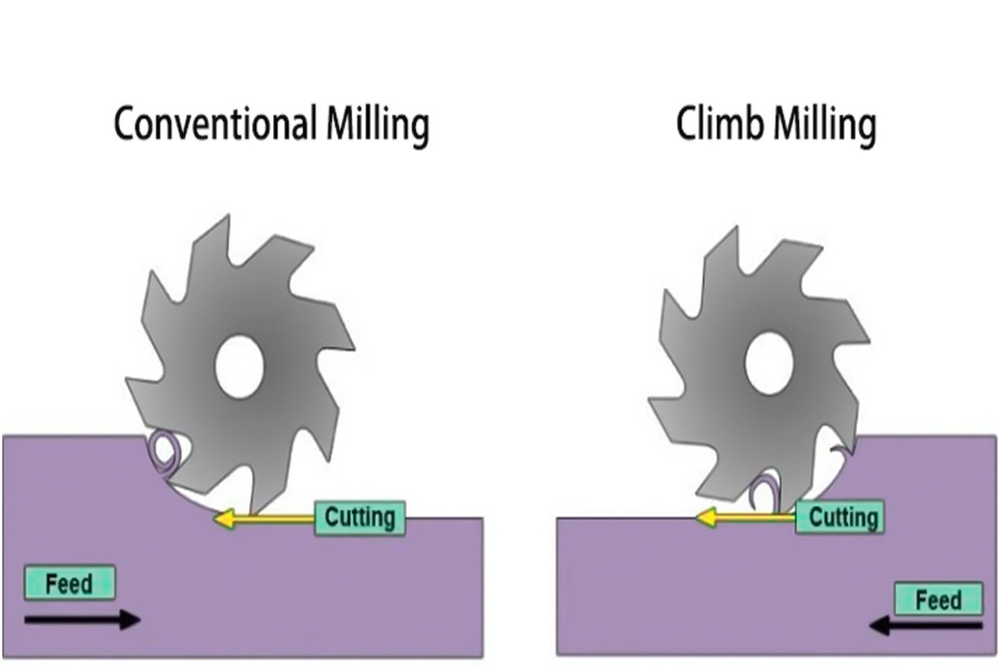
| Definition | The tool rotates in the same direction as the workpiece feed | The tool rotates in the opposite direction as the workpiece feed |
| Chip formation | Chip thickness changes from thick to thin | Chip thickness changes from thin to thick |
| Cutting force | The cutting force tends to press the workpiece against the worktable, and the cutting force is usually smaller and more stable | The cutting force tends to lift the workpiece off the worktable, and the cutting force fluctuates greatly |
| Surface quality | Usually better surface finish is obtained | The surface finish is relatively poor |
| Machine tool requirements | The machine tool must have good rigidity and no screw clearance | The machine tool clearance requirement is lower and more adaptable |
Key Concept Clarification: Please note that “Clamp Milling” is a common typo, the correct term should be Climb Milling. This is a key distinction to understand modern milling processes.
Conventional Milling:
The tool rotates in the opposite direction of the workpiece feed. The cutting edge “scrapes” from the material surface, starting with a minimal cut thickness and gradually increasing to a maximum. This causes the tool to be subjected to a large impact load when cutting in, and may “lift” the workpiece upward, requiring a more secure clamping. Chips are formed behind the tool.
Climb Milling:
The tool rotates in the same direction as the workpiece feed. The cutting edge “bites” directly into the material at the maximum cut thickness and then gradually decreases to zero. This method has a more stable cutting force, which is directed downward to press the workpiece against the worktable, which is beneficial for stability and surface quality. Chips are formed in front of the tool and are discharged.
Importance: Modern CNC machine tools, with their high rigidity, preloaded ball screws (eliminating backlash) and precise control systems, almost always prefer climb milling. Because it can significantly improve machining efficiency (higher feed/cutting speed), obtain better surface finish, extend tool life and reduce energy consumption. However, if the machine tool has screw clearance or insufficient rigidity, down milling will cause tool vibration, tool gnawing or even damage, and reverse milling must be used.
For modern CNC machine tools with sufficient rigidity and elimination of clearance, down milling is the standard milling method with better performance and more recommended.
Beyond the Basics: 3-Axis vs. 5-Axis Milling
| Features | 3-Axis Milling | 5-Axis Milling |
|---|---|---|
| Rotary Axes | None | 2 (A/B or B/C, etc.) |
| Clamping Requirements | Complex parts often require multiple re-clamping | Usually one clamping is sufficient |
| Processing Complexity | Medium (can complete plane, cavity, contour milling) | Very High (can process extremely complex curved surfaces, deep cavities, undercuts) |
| Applicable Parts | Relatively simple or parts that can be processed by faceting | Complex integral structures, impellers, blades, precision molds, etc. |
| Equipment Cost | Low | High |
| Typical Applications | Planes, slots, holes, simple curved surfaces, mold parting surfaces, etc. | Aerospace structural parts, complex medical devices, automotive molds, artworks, etc. |
3-axis milling:
- Basic: The most common and basic milling method, relatively simple to operate.
- Movement: The tool moves only along the three linear axes X, Y, and Z.
- Processing capabilities: It can effectively perform plane milling, cavity milling, and basic contour milling.
- Core limitations: The direction of the tool axis is always fixed (usually perpendicular to the worktable or parallel to the spindle).
- Complex parts bottleneck:
- When machining parts with multi-faceted features, deep cavities, undercuts, or complex surfaces, it is impossible to approach from the side or below.
- The workpiece must be repositioned and clamped manually or with a fixture multiple times to reach all surfaces.
- Main disadvantages: Repeated clamping increases operation time, labor costs, and introduces the risk of repeated positioning errors.
5-axis milling:
- Core upgrade: On the basis of the three linear axes X, Y, and Z, two rotary axes (such as A/B, B/C, etc.) are added.
- Revolutionary capabilities: The tool spindle direction and/or the worktable can be tilted and rotated, allowing the tool to approach the workpiece surface from any angle in space.
- Biggest advantage:
One clamping to complete processing: Even for extremely complex parts (such as integral impellers, precision mold cores, and complex curved surface structural parts), only one clamping is required to complete most or even all processing.
Key benefits:
- High precision: Eliminate the cumulative positioning errors caused by repeated clamping.
- High efficiency: Save multiple clamping adjustment time; optimizing tool posture can improve cutting efficiency and extend tool life.
- Unlock complex geometry: It can process undercut areas, deep and narrow cavities, continuous and smooth complex spatial surfaces, and other features that cannot or are difficult to complete with 3 axes.
- Positioning: Represents the top level of contour milling and complex part processing capabilities.
5-axis milling gives the tool all-round processing freedom through two rotating axes, allowing extremely complex parts to be fully processed with high precision and high efficiency in a single clamping, fundamentally solving the inherent limitations of 3-axis milling that relies on multiple clamping when facing complex geometries.
Case: Efficiently Manufacturing High-performance Aluminum Alloy Drone Fuselage Bracket
In a recent project undertaken by our company LS, we successfully processed a complex aluminum alloy drone fuselage bracket for the customer. The key features of this part include: high-flatness upper and lower mounting reference surfaces, external contours with weight-reducing special-shaped holes, and streamlined support arms that need to be precisely formed.
In order to achieve optimal performance (strength-to-weight ratio) and strict geometric accuracy requirements, we carefully planned and implemented the following professional processing strategies:
- Reference surface establishment (face milling): First, we use efficient face milling cutters to quickly and accurately process the upper and lower mounting reference surfaces of the part. This provides a reliable positioning and measurement basis for all subsequent processes and is the key first step to ensure overall accuracy.
- Contour and hole processing (peripheral milling): Next, we use end mills for peripheral milling. This step accurately processes the overall outer contour of the bracket and efficiently completes the roughing and finishing of the side walls and weight-reducing holes (including special-shaped holes) to ensure accurate dimensions and meet weight reduction requirements.
- 3D surface carving (contour milling): Finally, for the key streamlined support arm, we enabled advanced 5-axis simultaneous machining capabilities and used ball-end milling cutters for 3D contour milling. This strategy enables us to accurately move along complex surfaces and achieve the high strength and lightweight goals required by customer designs with optimized material distribution.
Value summary: This case clearly shows how LS can efficiently produce complex high-performance parts through systematic process planning and the comprehensive use of multiple milling technologies (face milling, peripheral milling, contour milling). Choosing the right processing sequence and matching tools/strategies not only directly determines the final quality and performance of the parts (such as the best strength-to-weight ratio and precise mounting surface), but also greatly affects the production efficiency and the final CNC milling price. This is exactly our core advantage as a professional online CNC milling service provider (online cnc milling services) – with our deep technical accumulation, we can provide customers with the most cost-effective and demanding manufacturing solutions.
FAQs
1. What is the difference between a milling operation and a milling machine?
A milling operation refers to a specific machining method or “what to do”, such as face milling (machining flat surfaces), peripheral milling (machining contour edges), or end milling (machining slots and cavities). A milling machine, on the other hand, refers to the physical equipment or “what to do” that performs these operations, and common types include vertical milling machines (spindle vertical), horizontal milling machines (spindle horizontal), and more advanced 5-axis machining centers (multi-directional movement).
2. How many types of milling are there?
There are three main core milling types: face milling, peripheral milling, and end milling. Although there are dozens of specific operations that can be broken down by tool (such as drilling, boring), tool path (such as spiral interpolation, contour milling), or workpiece features, these three categories cover the vast majority (about 99%) of actual industrial application scenarios.
3. What is “down milling” and why is it important?
Down milling means that the direction of tool rotation is the same as the feed direction. Its importance lies in: the tool gradually decreases from the maximum chip thickness to zero, reducing friction and cutting force, thereby significantly improving surface finish, extending tool life and reducing the risk of workpiece deformation. It is the preferred milling method for modern CNC machining (the machine tool needs to eliminate the gap).
4. Can one machine complete all three types of milling?
Yes, any standard CNC machining center (such as a three-axis vertical machining center) has the ability to perform face milling, peripheral milling and end milling. The key is to equip the right tool (such as a face milling cutter, end milling cutter) and write the corresponding machining program. Complex operations (such as 3D surfaces) require multi-axis linkage and more advanced programming, but basic milling types can be achieved.

Conclusion
Face milling, peripheral milling, and contour milling are the three core processes of modern CNC machining, which respectively create planes, refine side walls, and give parts complex shapes, and work together to transform digital designs into precision parts.
Understanding the differences between the three is conducive to communication with manufacturers, but turning designs into reality requires professional equipment, software, and engineer experience, and it is difficult to choose the right milling strategy in complex situations.
Stop guessing which type of milling is best for your parts! Leave the problem to our experts. Upload your CAD file to our smart platform immediately. Our system will automatically analyze the geometric features of the part, and the engineering team will plan the optimal processing path based on this (precisely combining face milling, peripheral milling, and contour milling processes) and provide you with an instant and transparent CNC milling quote. Experience a one-stop worry-free service from design to parts, making complex processing simple and efficient!
 📞 Phone: +86 185 6675 9667
📧 Email:info@longshengmfg.com
🌐Website:https://www.longshengmfg.com/
Disclaimer
The content appearing on this webpage is for informational purposes only. LS makes no representation or warranty of any kind, be it expressed or implied, as to the accuracy, completeness, or validity of the information. Any performance parameters, geometric tolerances, specific design features, quality and types of materials, or processes should not be inferred to represent what will be delivered by third-party suppliers or manufacturers through LS’s network. Buyers seeking quotes for parts are responsible for defining the specific requirements for those parts. Please contact to our for more information.
Team LS
This article was written by various LS contributors. LS is a leading resource on manufacturing with CNC machining, sheet metal fabrication, 3D printing, injection molding,metal stamping and more.


