

Sheet metal fabrication is a core aspect of advanced manufacturing that transforms metal sheets into desired structures. Its emerging importance in industries like aerospace and automotive makes it a must-understand principle.
Therefore, this guide explains how to fabricate sheet metal parts and types of fabrication designs. We also discuss machining tolerances, principles of metal sheet manufacturing, types of metal sheets, and surface finishes for your next sheet metal parts project.
What is sheet metal fabrication?
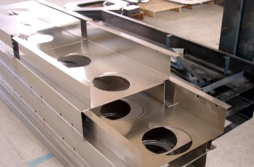
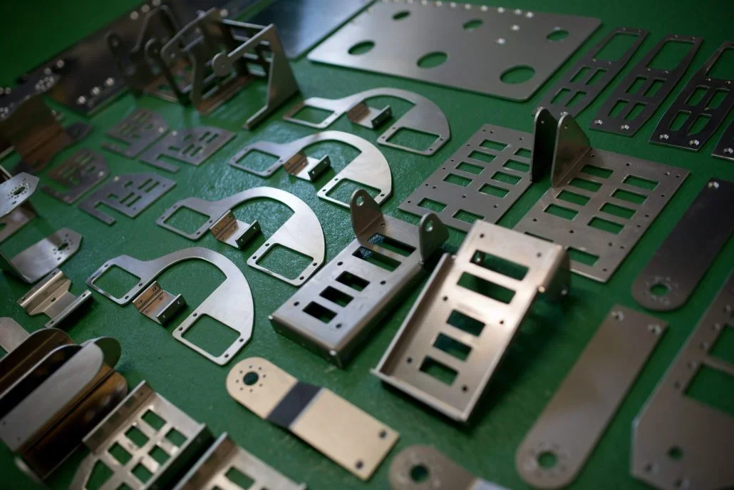
Sheet metal fabrication is the process of converting flat metal sheets like aluminum, copper, steel, or brass into manufactured parts. The different techniques to shape sheet metals include cutting, bending, stamping, and punching.
How to fabricate sheet metal parts?
The sheet metal fabrication process is a step-by-step approach that starts with determining the design requirements. It includes considering dimensional constraints, after which you choose the material for fabrication design. Subsequently, you create fabrication design blueprints that present sketches of the structure and geometry of sheet metal parts on paper. The creation of computer-aided design (CAD) comes next, where you have the model drawn to scale. Additional steps include considering the design for manufacturability (DFM), which involves evaluating manufacturing constraints, simplifying part geometries, and optimizing the number of manufacturing operations.
The Main Advantages and Disadvantages of Using Sheet Metal for Fabrication
Sheet metal parts designs are quite popular in many industries because of their perceived advantages. However, there are multiple limitations to the process as well. These advantages and limitations are among the most important design considerations for manufacturers as they determine the correct applications of the metal.
| Advantages | Disadvantages |
| Fast manufacturing times | High labor costs for some metal fabrication processes |
| High strength-to-weight ratio of fabricated sheet metal parts | High initial capital to set up some processes like stamping |
Versatile compatibility with many metal materials |
Types of sheet metal fabrication techniques
We can divide the different techniques for manufacturing sheet metal parts into two important categories: cutting sheet metal and forming sheet metal.
Cutting is a fabrication process that removes excess sheet metals from the block material to produce custom metal parts. We have the cutting with shear and cutting without shear techniques.
1.Cutting without shear
There are three types of sheet metal fabrication under the cutting without shear method.
A.Laser cutting
There are three types of sheet metal fabrication under the cutting without shear method.
a.Laser cutting
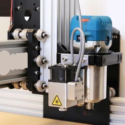
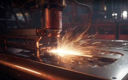
Laser cutting is a CNC precision metal fabrication method that uses high-powered laser beams to cut metal sheets. The laser resonator generates a high-intensity (infrared) beam and directs it to the cutting head through mirrors or fiber optics.
Subsequently, the focused beam (0.15 – 0.41mm) melts the sheet metals along the predetermined cutting line using oxygen or nitrogen gas to remove molten materials.
b.Plasma cutting
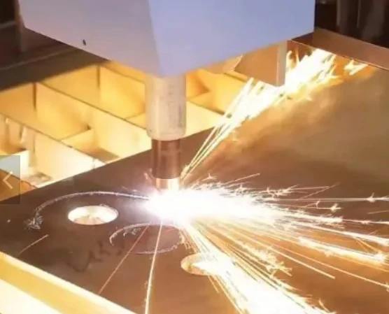
Plasma cutting is a sheet metal fabrication process suitable for thicker and only electrically conductive metal sheets. So, how does plasma cutting work?
It starts by passing gas (compressed air) through a nozzle at high speed to create an electrical arc. The formed arc ionizes the gas to heated plasma that melts the sheet metal parts while the compressed gas blows away the molten parts for clean, precision cuts. Plasma cutting does not have better surface finishing than laser cutting.
c.Water jet cutting
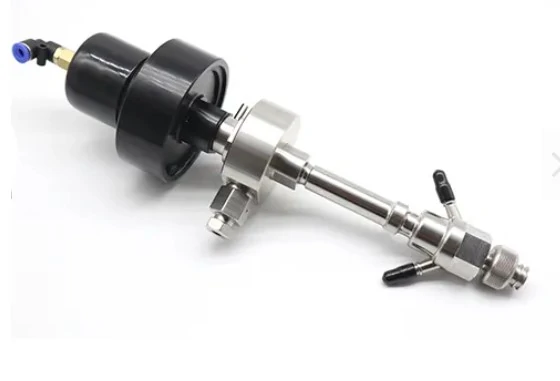
Water jet cutting is a type of sheet metal fabrication process that uses specialized pumps to generate high-pressurized water (about 60,000 psi). The water is mixed with abrasives like garnet to enhance cutting ability as the mixture is ejected at high velocity through a nozzle, cutting the fabricated sheet metal. Water jet cutting has excellent surface finishing.
B.Cutting with shear
Cutting with shear is the type of sheet metal fabrication process that involves using a die to hold or support the material during cutting. The “cutting with shear” method involves:
a.Shearing
Shearing of fabricated metal sheets is when a straight line is cut through the material to separate it into two. This method combines manual hand power, electricity, and hydraulics depending on the length and thickness of the sheet metal parts.
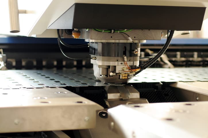
b.Punching
As described for general cutting with shears, punching involves holding the fabricated sheet metal parts with a die and punching through. The stock is the part that remains on the die, while the scrap material is that which gets punched off.
c.Sawing
Sawing in the fabrication of sheet metal parts involves using the sawtooth tool to divide a portion of material from the rest through shear forces and friction.
Forming sheet metal
Forming is an essential sheet metal fabrication technique. The objective is to achieve a finished product and improve the strength and stiffness of the parts assembly. Forming sheet metal is divided into bending, stamping, and punching.
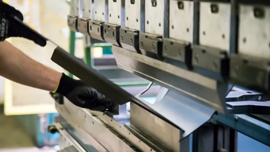
Bending
Bending is a precision metal fabrication method that involves deforming the workpiece along a straight axis, creating a V-shape, U-shape, or channel shape. Specialized machinery like press brakes is commonly used and requires professional machinists for precision manufacturing.

Stamping
Metal stamping is a forming method or sheet metal fabrication process that utilizes a die and punch to create desired shapes or profiles. The die is forcibly pressed against the sheet metal that forms the die cavity. It is helpful for complex shape geometries and embossing.
Punching
The punching sheet metal fabrication process differs from the stamping method. For punching, a “punch” is applied against the sheet metal, piercing it to create desired holes or shapes. It is a technique for making holes or perforations in sheets.
Tolerances for different sheet metal fabrication design
Tolerance values represent the allowable difference (if any) between the intended and specified values. The following table provides the tolerance specifications for certain sheet metal manufacturing features.
| Sheet metal design features | Tolerance values |
| Wall thickness | 0.9mm to 20mm |
| Bends | 0.9mm to 1.2mm, 1.8mm to 2.4mm, 3.8mm to 5mm, 7.5mm to 10mm, 15mm to 20mm |
| Holes and slots | Diameter > material thickness |
| Offsets | 0.3mm to 0.7mm |
| Hems | Inside diameter = material thickness, and thickness should be 0.25 x thickness |
| Curls | >2x material thickness |
| Machined countersink diameter | Major diameter = +/- 0.254mm (with 2.3mm to 12.7mm recommended lengths)Minor diameter = ⅔ thickness |
| Formed countersink diameter | +/- 0.381mm (major and minor diameters) |
| Notches and tabs thickness | Notch width > 1.5x thicknessLength > 5x thickness |
| Curls | >2x material thickness |
Countersink holes and tolerances
We have the formed countersink holes created with punch press tooling and the machined countersink holes via drill press. However, the maximum industry standard for countersink depths is <0.6mm x material thickness and tolerance details are in the table above.
Bends
Machinists typically manufacture sheet metal bending at +/-1 degrees of tolerance values. The table above contains the tolerances for the different radii bends.
Notches & tab
The minimum dimensions for notches are their material thickness. Check the table above for more information regarding the tolerance of notches & tabs.
Curls
Curling is a sheet metal fabrication process that involves the addition of a hollow but circular roll to sharp material edges to improve safe handling.
Holes and Slots (ISO standards)
Do not allow the diameter of holes and slots to be lower than the material thickness. Besides, ISO 16630:2009 provides a 1.2mm – 6.0mm thickness range and a minimum width of 90mm for metallic hole expansion ratio.
Kerfs from laser cuts
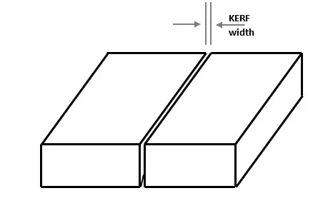
Kerf is a sheet metal fabrication design term that describes the “left-out gap” or width of material that becomes scrap when the laser cuts a material block. Kerf values generally range from 008 – 0.45 mm. Therefore, it is good practice to leave out about 1mm distance from the cutting edge to avoid crossover cuts.
ISO standard for sheet metal design
The general industry standard for sheet metal fabrication design is ISO 2768. It includes the required tolerance specifications for various industrial applications of metal parts.
Rule of thumb for sheet metal bending
Always ensure the internal bend radius is not less than the thickness of sheet metal parts to prevent fractures or deformations during metal fabrication.
Principles of sheet metal fabrication process
Learn the basic principles that guide how to fabricate sheet metal parts for your next manufacturing projects.
1.Avoid CAD files with sharp internal corners
One serious mistake in sheet metal fabrication design is having a CAD file with sharp internal corners. You should include bends and indicate the bend angles to prevent stress concentration and material deformation.
2.Forgetting the 4T rule for design features
Placing design features like holes too close to a bend can also cause deformation or cracking of sheet metals during bending. Hence, following the 4T rule, all features must be at least 4x material thickness distance from bends.
3.Don’t skip hardware dimensions in the CAD file
A fundamental principle of the sheet metal fabrication process is to include all necessary hardware specifications and dimensions. Otherwise, there would be unwanted stops in production.
4.Do not overlook tolerances
Failure to consider tolerances in the CAD design and implementation would cause inaccuracies and affect the quality of manufactured sheet metal parts.
5.Always choose the correct sheet metal material
Confirming the material properties with the expected functionality of the fabricated sheet metal parts is another vital principle of the sheet metal fabrication process.
6.Consider the material thickness
Inadequate material thickness for fabricated sheet metal parts manufacture causes structural weakness and compromised durability.
Important parameters for bending during sheet metal fabrication design
These are the essential parameters you must understand about sheet metal bending processes.
1.Bend line
The bend line represents a straight line across the surface of the metal sheets, indicating the start and end points on both sides. The industry bend line standard is 5x the thickness of sheet metal distance between the internal and external edges of the bend.
2.Bend angle
The bend angle is the orientation between the sheet metal bend and an imaginary line perpendicular to its axis. The general industry standard is keeping all bend angles equal for the same fabrication design.
3.Bend radius
The bend radius is the distance between the bending axis and the internal surface of fabricated sheet metal parts. It should have a minimum length equal to the material thickness.
4.Neutral axis
The neutral axis is the sheet metal part that does not stretch or compress during bending.
5.K-factor
The K-factor for sheet metal bending is typically around 0.25 – 0.5mm and is expressed mathematically as the neutral axis to material thickness ratio. It is sometimes difficult to accurately estimate since it depends on parameters like bend angle and material type.
Common materials used in sheet metal fabrication process
Read about the standard material types for your CNC-fabricated sheet metal projects.
1.Stainless steel
Stainless steel material types for sheet metal fabrication and design are durable, cost-effective, and have excellent mechanical strength.
2.Copper
While copper is expensive, its excellent durability, thermal properties, and chemical resistance make it a popular type of material for fabricated sheet metal parts.
3.Aluminum
Aluminum is an excellent pick for sheet metal fabrication design when an effective strength-to-weight ratio is a priority.
4.Brass
Brass is an alloy of copper and zinc, which indicates its combined hardness and corrosion resistance properties.
5.Pre-plated steel
Pre-plated steel is similar to regular steel except that it has undergone coating with another metal, usually zinc. Hence, it has enhanced corrosion resistance and can withstand harsh weather.
Important factors that influence material selection for sheet metal fabrication design
This section explains how to fabricate sheet metal parts by selecting the correct materials for the manufacturing process.
1.Mechanical properties
When choosing sheet metal fabrication design, consider mechanical properties like tensile strength, flexibility, and toughness.
2.Corrosion resistance
The ability of the material to resist corrosion is essential for fabricated sheet metal parts for outdoor applications or high-pressured environments like aerospace.
3.Machinability
Otherwise referred to as formability for sheet metal parts processing, machinability measures how easy it is to shape or form a material without deformation. Good machinability implies faster production and a lesser cost of sheet metal fabrication.
4.Cost
Yes, the cost of your preferred sheet metal materials for design fabrications significantly affects the decision-making. However, always opt for metal choices that provide a fair mix of specifically required properties.
5.Aesthetics
This selection factor relates to the appearance of the sheet metal materials. Aesthetics also help to determine the surface finish texture.
The table below contains essential material selection factors for sheet metal fabrication design.
| Sheet metal material | Machinability | Tensile strength (Yield, Ultimate) in MPa | Corrosion resistance | Cost |
| Stainless steel 304 | Excellent | 215, 505 | Good | $$$$ |
| Stainless steel 316L | Good | 205, 515 | Excellent | $$$$$ |
| Copper 110 | Poor | 69, 221 | Good | $$ |
| Aluminum 5754* | Good | 215, 270 | Excellent | $ |
| Brass (alloy) | Excellent | 34.5 – 683, 20.7 – 1030 | Excellent | $$$ |
Finishing and surface treatments in sheet metal fabrication design
Although it is possible to have fabricated sheet metal parts without finishing treatments, it is often necessary. The following are the commonly applied surface finishing services.
- Anodizing
- Powder coating
- Polishing
- Chromate conversion coating
- Bead blasting
- Vapor polishing
- Black oxides
- Brushing
How to join fabricated sheet metal parts
Check out the standard methods for joining manufactured sheet metal parts after the fabrication design process.
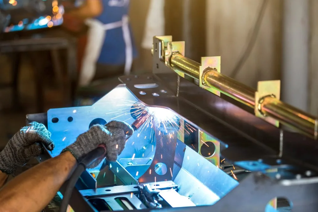
1.Welding
Welding in joining fabricated sheet metal parts fuses two or more metal pieces by applying high temperature and pressure. Welded metallic sheets are usually strong with long-lasting bonds. The typical welding techniques are MIG (Metal Inert Gas), TIG (Tungsten Inert Gas), Spot and Seam welding.
2.Soldering
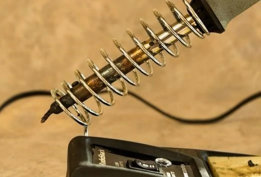
Soldering differs from the welding technique of joining fabricated metal parts since the base metal sheets do not melt. Instead, a filler metal with a lower melting point is melted and applied between the two metal surfaces to be fused.
3.Fasteners
Fasteners are different from soldering or welding because they are for non-permanent joints. Examples of fasteners include nuts, hooks, panel screws, and cable-tie mounts for joining fabricated sheet metals that might require detachment later.
Popular applications of sheet metal fabrication design
Fabricated sheet metal parts have lots of practical usage in the following areas:
- Aerospace precision parts
- Automotive metal parts
- Medical industry precision parts
- Industrial equipments
- Electronics
Longsheng: Your trusted sheet metal fabrication design company
That is all about this sheet metal fabrication design guide. We hope you found it helpful and understand how to plan your upcoming CNC fabrications of sheet metal parts project.
Remember you can contact us via email or phone with related questions, and our professional engineers will readily reply. We also offer CNC machining and 3D printing services at the best value for money to help you stand out in your industry.
FAQs
What are the best practices in the sheet metal design process?
Best practices for sheet metal design include material selection, bending radius, relief cutting, tolerances and tolerances. By designing bending, folding, and joints to satisfy mandrel constraints, we can ensure manufacturability.
What is the most suitable material for sheet metal design?
Select sheet metal materials based on the required strength, corrosion resistance, and cost. When making this choice, consider the design requirements, the operating environment, and any regulations or standards to be met.
What common mistakes are often made in sheet metal design, and how to avoid them?
Insufficient bending radius and incorrect tolerances are common sheet metal design errors. Other errors include ignoring material characteristics or designing welds with an inefficient joint structure. Understanding the design requirements, conducting feasibility studies, and complying with the design guidelines are essential to avoid early errors.
Can the CAD software help to complete the sheet metal design process?
CAD software provides powerful tools to design, modify, and analyze sheet metal design. The software allows designers to visualize and verify the design before production, optimize material use, simulate the molding process, generate accurate manufacturing documents, simplify design processes and reduce errors, collaborate with design teams and manufacturers and create the right documents.
What is the development prospect of sheet metal design?
Improvements in forming processes, manufacturing techniques and materials will lead to improvements in design complexity, precision and efficiency. The algorithms based on artificial intelligence (AI) and machine learning will further optimize the design while shortening the development cycle.
resource